Product Overview
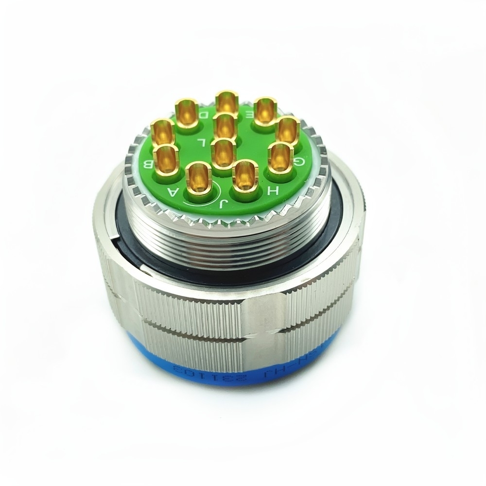
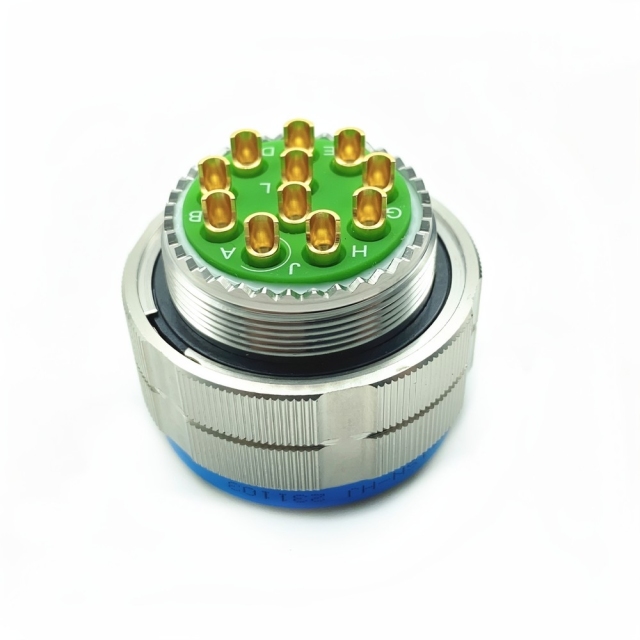
Built around a machined shell. The body is a lightweight aluminium alloy shell with cadmium plating, cut with a triple-start thread. Three starts mean the coupling takes up in a short turn rather than several, which matters when the plug has to be mated behind a panel or inside a bay where there is no room to rotate a hand. Full engagement is visible and tactile, so the technician knows the coupling is home rather than guessing at it. Insert and contacts. Inside, a bonded insert holds gold-plated copper alloy contacts in a fixed geometry. Because the insert accepts mixed contact types — signal, power, coaxial and high-speed data — one shell can serve several circuits instead of three connectors competing for the same panel space. Plug and socket format. This is an aerospace plug socket connector in the literal sense: the plug carries socket contacts in this configuration, and the matching receptacle of the same shell size and layout carries the pin side. Keeping the two halves complementary by design is what allows the cable half to be built, tested and swapped without re-terminating the fixed side of the coupling. Confirm the ingress rating your own specification calls for when you order — the class required can differ between an equipment bay and an exposed deck position. The MIL-DTL-38999 Series III connector is the interface a programme specifies when the connection has to survive the platform rather than the bench: continuous vibration, shock loads from stowed equipment, temperature swings from cold soak to engine-bay heat, and years of moisture and salt exposure. Series III sits at the high-reliability end of the 38999 family, with a threaded coupling, a keyed shell and a controlled contact system that keeps signal and power paths steady while the cable bundle around them moves. This part is the cable-mounted half: a shielding plug with crimp socket contacts and an olive green cadmium finish, built to mate with the matching Series III receptacle of the same shell size and contact layout. That split is why the format is used so widely on aircraft and vehicle builds — the panel half is installed and wired early, while the cable half is assembled on the bench, brought to the airframe and often remade several times over the life of the platform without disturbing the receptacle. OEMs, panel builders, systems integrators and depot teams all work from the same starting point, which is the part number written on the drawing. When the plug, the receptacle and the spares list all reference the same interface, a replacement ordered years later still mates first time. That continuity is the practical reason programmes standardise on this interface rather than on whatever connector happens to be in the stores cabinet that week. Sourcing matters here as much as the specification. A MIL-DTL-38999 supplier that builds the shell, plates the contacts and assembles the cable in one place can keep a variant consistent from the first prototype lot to the hundredth production order, and can tell you what changed if anything did.
Key Advantages
- Coupling that stays home under load. The threaded shell takes up hard against the receptacle and stays there through sustained vibration and shock, so the contacts of a vibration resistant circular connector are not worked loose by the platform underneath them.
- Plated for salt air and condensation. The cadmium-plated aluminium shell and gold-plated contacts are specified for salt-laden atmosphere and repeated wet-dry cycles, so a salt spray resistant connector does not turn into a quarterly maintenance item.
- Dense wiring without a bigger panel. A compact circular shell with a mixed insert means several circuits share one cut-out on a single aerospace plug socket connector, which is how a crowded bay stays serviceable instead of turning into a bundle of separate connectors.
- Repairable rather than disposable. Keyed mating and crimp contacts mean a damaged lead can be re-terminated on the bench; the shell and the wiring bundle around it do not have to be scrapped with it.
Part Number Reference
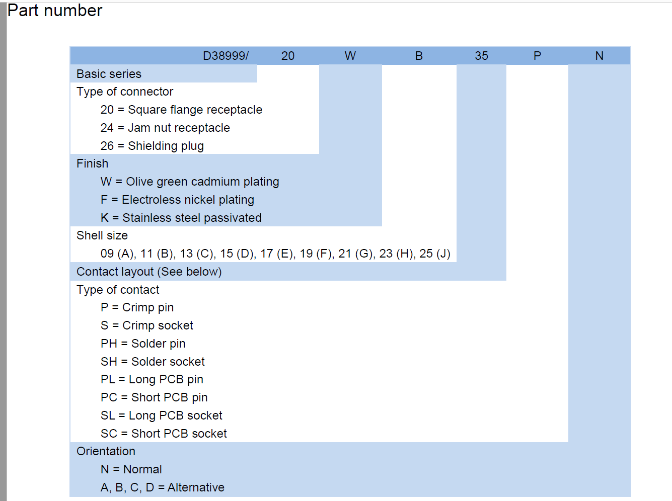
Reading the designation back is the quickest way to check that what arrives matches what the drawing asked for — the sort of check a military circular connector supplier should be able to make from the part number alone. In D38999/26WG11SN, the 26 field sets the connector type — shielding plug — so this is the cable-mounted half of the pair. W is the finish: olive green cadmium plating. The same shell also comes in F, electroless nickel, and K, passivated stainless steel, for builds that call for a different surface. G is the shell size, the 21 position inside a range that runs from 09 through 25 and is lettered A to J. 11 is the contact layout within that shell. S gives the contact style, crimp socket, which means the contact is crimped to the wire and pushed into the insert rather than soldered in place. The closing N is the keying orientation — normal; A, B, C and D let the same MIL-DTL-38999 Series III connector be clocked differently, so two adjacent assemblies cannot be cross-mated on one panel. The shell and insert also carry across the rest of the range: 20 is the square flange receptacle and 24 the jam nut receptacle, and contacts are available as crimp pin or socket, solder pin or socket, and long or short PCB tails.
Critical Applications
- Armoured and mobile platforms. Inter-vehicular and turret harnesses take constant shock and road vibration; a vibration resistant circular connector holds its coupling where a push-pull body would creep apart, and the plug can be replaced at a depot without pulling the hull loom.
- Avionics bays and engine control. Line-replaceable units, flight data recorders and engine-control harnesses need a MIL-DTL-38999 Series III connector that survives pressure cycling and bay heat, and still mates on a rail in a confined space.
- Missile, radar and field communications. Guidance and radar assemblies are sealed and potted around their connectors, so the interface has to be right the first time and stay right through storage and transport.
- Unmanned aircraft and satellite subsystems. Payload and bus wiring is dense and hard to reach once integrated; the compact footprint and keyed mating reduce the chance of an assembly error that cannot be corrected later.
- Naval and coastal installations. Deck boxes, masthead equipment and harbour-side cabinets live in salt-laden air, which is where a salt spray resistant connector with a plated shell and gold contacts keeps the interface readable and serviceable across repeated deployments.
- Heavy machinery and process plant. Offshore, mining and washdown areas bring moisture, grit and cleaning cycles, the conditions in which a waterproof military circular connector earns its place on equipment that is otherwise ordinary industrial hardware.
- Emergency response and medical life support. Field ventilators, rescue communications and mobile treatment units need connectors that tolerate being packed, dropped and stored between deployments.
Use Scenarios
Take an avionics rack on a commercial-derivative airframe. The keyed shell means the wrong cable cannot be pushed home, and the thread tells the technician when the coupling is seated instead of leaving them to judge it by resistance. Now a depot floor, where a vehicle wiring loom comes back with a crushed plug and a length of damaged cable. Then a dockside control cabinet on a crane, where a salt spray resistant connector sits in salt air, takes spray off the deck and is opened twice a year for inspection. On a test bench the story is repetition: an assembly may be mated and unmated dozens of times during qualification, and the contact system has to read the same on the hundredth cycle as on the first. Where a programme needs a steady supply of the same part for that kind of work, a military circular connector supplier that holds the shell and insert tooling is a simpler arrangement than chasing stock across distributors.
Specifications
| Parameter | Specification |
|---|
| Series | MIL-DTL-38999 Series III |
| Connector type | Waterproof military circular connector; shielding plug (code 26), cable-mounted half |
| Shell size | 21 (code G) |
| Contact layout | 11 |
| Contact type | Crimp socket (code S) |
| Keying | Normal (code N); A–D alternate positions available |
| Shell material | Aluminium alloy, olive green cadmium plating |
| Contact material | Copper alloy, gold plated |
| Current rating | Up to 5 A per signal contact; 23 A on power positions |
| Voltage rating | 1,500 V AC RMS |
| Operating temperature | -65 °C to +200 °C |
| Moisture protection | Sealed interface, IP67/IP68 class |
| Coupling | Triple-start thread |
Contact Termination & Tooling
- Crimping, not soldering, is what sets the electrical and mechanical quality of this plug. The socket contacts are crimped with a tool and die matched to the contact size, and the result is checked against the tool's crimp-height gauge. An under-crimped barrel pulls off the wire under load; an over-crimped one cracks the plating and raises resistance at the joint — both surface later as a fault the platform gets blamed for.
- A clean crimp starts at the strip. Cut back to bright, undamaged conductor, strip to the length the contact barrel calls for, and keep every strand. Insulation must stop short of the crimp barrel, and no nick or ring cut should be left on the conductor where it enters the contact.
- Seat each contact with an insertion tool, from the rear of the insert, until it clicks past the retention clip. Pushing a contact in by hand or with pliers rarely seats it fully and often damages the tines that are supposed to hold it.
- Pull-check every position after insertion.
- Rework with a removal tool, never with grips. Pulling a contact out by force spreads the retention tines and leaves that cavity unable to hold its replacement; a damaged lead should be cut back, re-crimped and re-inserted properly.
- Keep the contact and the sealing face clean. Gold-plated copper alloy contacts should not be handled on the barrel ends, and the interface should be capped or bagged whenever the shell is off the cable, because grit or dried compound on the sealing face is what lets moisture past a seal that is otherwise sound.
- Close the coupling fully before the assembly goes back into service. Line the keyways up first, then take the triple-start thread home by hand until it seats; part-way engagement leaves the seal uncompressed and the contacts free to work under shock.
- Build the order to match the bench. Loose crimp socket contacts, spare contacts for rework and the mating receptacle can all be quoted with the plug, so the cable assembly shop is not waiting on a single contact before a cable can be released. Tell us at quotation whether your team already holds the crimp and insertion tooling for this contact size — if not, say so and we will confirm what is needed before the order is placed.
Ordering & Delivery
- Send the full part number and the quantity. Include the split between plugs, receptacles and loose contacts, and note any alternate keying — ordering direct from a MIL-DTL-38999 supplier means the whole kit can be quoted in one pass instead of being assembled from three catalogues.
- Confirm the configuration field by field. We check connector type, finish, shell size, contact layout, contact style and key position against your drawing, and flag anything that does not line up before the order is released.
- Agree documentation and packing. Lot identification, traceability records and test documentation travel with the shipment; if your goods-in team needs a particular packing method or marking, say so at quotation so it can be built into the order.
- Agree the commercial terms. Price is quoted per part number and quantity, and payment method, shipping terms and lead time are confirmed at quotation. Flexible MOQs mean a single plug for a repair and a full build-line release are both workable.
- Plan delivery around the build. Stable global delivery keeps a programme supplied from one source, and repeat orders are scheduled against the same part number so the second shipment matches the first.
Technical Support & Model Matching
Selecting the right connector is rarely a one-line decision. Send us your drawing, part number or a sample, and our engineering team will confirm the matching shell size, contact arrangement, coupling and mounting style, cross-reference discontinued or alternate part numbers, and advise on sealing and flange options for your environment. We also help troubleshoot fit, mating and signal problems, and give installation and commissioning guidance so your line stays up. As a direct manufacturer, our answers come from the people who build the parts — from first enquiry through after-sales support.
Three things decide whether a connector programme runs smoothly: the part arrives as specified, the paperwork stands up to scrutiny, and the next order arrives the same way as the first. We build these connectors in our own plant rather than buying them in, so the shell, the plating and the contact configuration are controlled at the same source that signs the documentation. Every unit is checked for sealing and vibration performance before it leaves the line, and shipments travel with the lot identification and traceability records a defence programme expects to see at goods-in. For parts headed into controlled defence applications, export paperwork is handled under ITAR/ECCN procedures rather than being sorted out after the crate has landed. Working with a MIL-DTL-38999 supplier that also builds cable assemblies shortens the loop. The plug, the mating receptacle and the terminated leads can come as one kit, which removes the mismatch risk that appears when three vendors each supply a piece of the same interface — and keeps the maintenance plan realistic, because a damaged lead becomes a known part number instead of a re-engineered assembly. The wider range matters too. This connector sits inside a line that covers MIL-DTL-38999 Series I to III, MIL-DTL-26482 Series I and II, and rectangular and fibre-optic bodies as well, so a programme standardising on one source can equip several interface types without opening a new supplier file for each. If you need a second source against an existing drawing, or a part that has to mate with hardware already in the field, bring the drawing and the shell, insert and key details early — it is straightforward while the cable assembly is still on paper and much harder once it is built.
FAQ
What makes this connector suitable for harsh operating environments?
The interface is sealed, the shell is plated aluminium alloy and the contacts are gold-plated copper alloy, so vibration, salt spray, high temperature, shock and water exposure are handled by one assembly rather than by add-on protection. The threaded coupling seats fully and holds the two halves together while the platform vibrates, and the insert maintains contact force across the -65 °C to +200 °C range. In practice that is what allows a waterproof military circular connector of this size to sit on an exposed deck or in an outdoor cabinet for years between inspections.
Is this connector appropriate for aerospace and military wiring systems?
Yes. The plug is built to MIL-DTL-38999 Series III and is used in avionics bays, vehicle harnesses, naval equipment and field communications, where the interface has to stay stable under vibration and temperature change. It is also the format most often specified when a new build has to stay backward compatible with equipment already in service. We supply it as a military circular connector supplier into new-build programmes and depot replacements alike, and we check the mating half against the same drawing whenever a customer is matching an existing receptacle.
Which half of the coupling is this, and what does it mate with?
It is the plug — the cable-mounted half of an aerospace plug socket connector pair, fitted with crimp socket contacts in this configuration. It mates with the Series III receptacle of the same shell size and contact layout, which carries the complementary pin contacts. Shell size, contact layout and key position must all match between the two halves; if the fixed side is being specified at the same time, the same shell is available as a square flange or a jam nut receptacle.
What contact styles and finishes can be supplied in this shell?
The shell can be supplied with crimp pin or socket contacts, solder pin or socket contacts, and long or short PCB tails, so the same body serves a crimped cable assembly, a soldered repair or a board-mount position. Finishes include olive green cadmium plating (W, as supplied here), electroless nickel (F) and passivated stainless steel (K). Tell us which finish your drawing specifies — the three are not interchangeable in service, and the cadmium version is the one most often called for when corrosion resistance drives the requirement.
Does the plug need special tooling to terminate?
Yes. Crimp socket contacts are terminated with a crimp tool matched to the contact size and then inserted with the correct insertion tool, rather than soldered in place. Using the right die and a controlled crimp height is what preserves the current rating and the contact's resistance to vibration. Push each contact in until it clicks into the insert, then give a light pull-check before the shell goes back on; a partly seated contact is the most common cause of an intermittent circuit on a newly built cable assembly.
Will the coupling stay tight under continuous vibration?
It will, provided it is fully seated. The triple-start thread takes up against the receptacle, and the coupling is designed to stay engaged through sustained vibration and shock, which is why the format is specified wherever a vibration resistant circular connector is a stated requirement. Secondary retention such as safety wire or a lanyard is not part of the coupling as supplied; if your installation procedure calls for it, tell us when you order so the right accessory is quoted alongside the connector.
Can the seal be restored after a repair or re-termination?
Yes, as long as the sealing components are reused or replaced and the shell is fully seated on reassembly. The seal sits in the interface, so it is disturbed whenever the plug is opened: inspect the sealing face for grit or damage, keep the contacts clean, and close the coupling firmly rather than nipping it part-way home. If a connector has been opened in the field, a bench check of contact resistance before it goes back into service is worth the ten minutes.
Is the connector supplied with the matching receptacle and contacts?
It can be. Plugs, matching receptacles and loose contacts are all part of the range, so a complete cable assembly can be kitted from one order rather than three. As a D38999 connector manufacturer we hold the shell and insert tooling for the series, which is what allows the mating half to be matched to your drawing instead of guessed from a catalogue. Send the part number for both halves and we will confirm they pair correctly before the order is released.