Product Overview
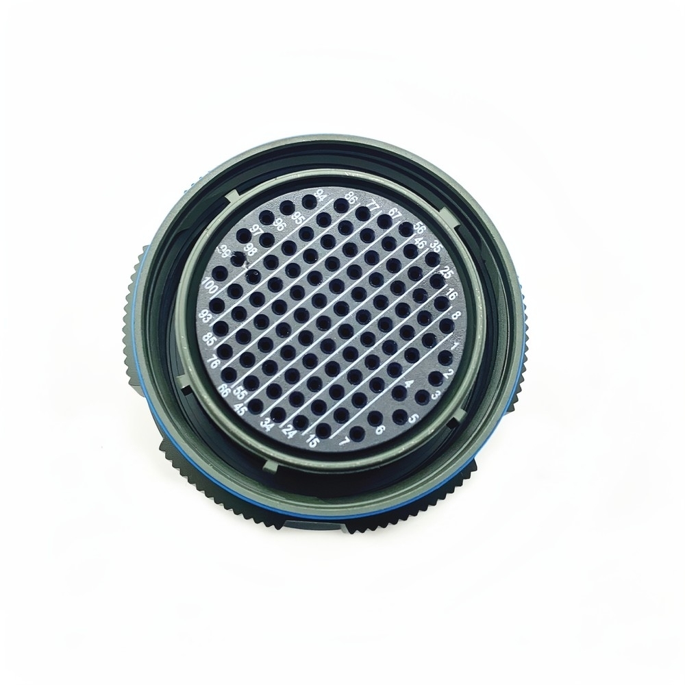
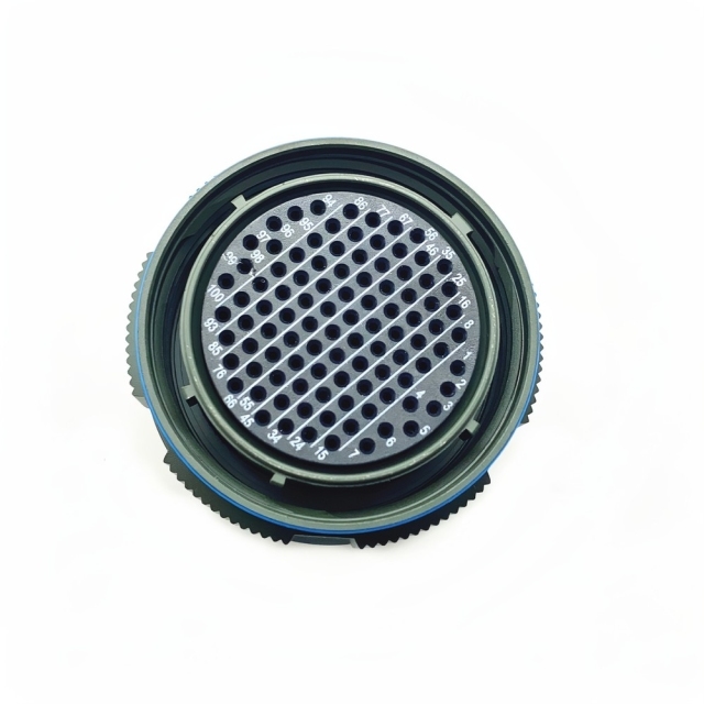
The D38999 26WH35SC connector is the cable half of a MIL-DTL-38999 Series III coupling — what the part number calls a shielding plug. In service the plug is the half that travels with the cable assembly, while the receptacle — a square-flange or jam-nut body of the same shell size, layout and keying — stays bolted to the equipment. That split is why the plug is usually the part replaced when a cable is damaged in the field, and the part worth keeping on the shelf as a spare.
Electrical & Environmental Ratings
- Held under vibration. A triple-start thread keeps the coupling loaded instead of relying on friction alone, so contact pressure stays where it was set on engine-adjacent, vehicle-mounted and rotating-equipment wiring. That is the job a vibration resistant 39999 connector is bought for.
- Plated for salt exposure. The aluminium shell carries the cadmium plating the W code calls for, which is why this pattern is specified as a salt spray resistant connector on deck, dockside and coastal installations where untreated metal would soon corrode.
- Temperature headroom. Insert and shell hold their dimensions and their contact pressure through the heat soak of an engine bay and the cold of high altitude, so the mated interface does not loosen as the assembly cycles.
- Shock without a lost circuit. The shell takes the impact and carries the load around the insert rather than through the contacts, so a knock on a bulkhead or a drop during handling does not turn into an intermittent circuit.
- A standard interface, not a new one. The shell and coupling follow the MIL-DTL-38999 Series III geometry, so the D38999 26WH35SC connector fits the receptacle already called out on the drawing and any test adapter built for that interface.
- Built in our own production. We manufacture this plug as a military circular connector supplier rather than reselling distributor stock, so the shell, insert, contacts and plating on your order come off one line and can be checked together before dispatch.
Contact, Insert & Mating Half
This is the plug half of an aerospace circular connector plug socket pair, and it follows the usual 39999 convention: the S code means crimp socket contacts, so the sockets travel with the cable and the equipment-side receptacle is the half fitted with pins. The socket contacts accept those pins as the coupling closes, and the insert retains each contact in its own cavity while the shell carries the mechanical load — the split a mil-dtl-38999 connector manufacturer has to get right, so that contact retention never depends on shell strength.
The 35 layout sits in a size 11 shell, and the layout — not only the shell size — is what has to match on the other half. A receptacle built to a different layout will not present its pins to the right cavities, so order the mating half by shell size and layout together rather than by description. Where an assembly mixes signal and power, tell us the contact sizes the design calls for and we will confirm what the insert can carry.
Crimp termination is what makes this version attractive to cable assembly shops. Strip, crimp with the tooling matched to the contact, push the contact into the insert from the rear until it seats, then give it a light pull to prove it is retained — the check a vibration resistant 39999 connector is really judged on. A seated contact can be extracted again with the right tool, so one damaged circuit is repairable without scrapping the plug.
The seal is the quiet part of the design. Once the halves are drawn together the interface seal is compressed and the contact chamber is closed, which is what turns the sealed shell into a waterproof military circular connector rather than a splash-resistant one. Keep the seal clean and undamaged at every re-mate; grit trapped on the seal is the usual cause of a leak.
Keying is the last check before the halves go together. This plug is built in orientation C, one of the alternative keying positions, so the receptacle must be keyed to match. Align the keyway notch, push the halves together and turn the knurled coupling ring until it seats — the thread does the pulling, and no tools are needed.
Part Number Structure
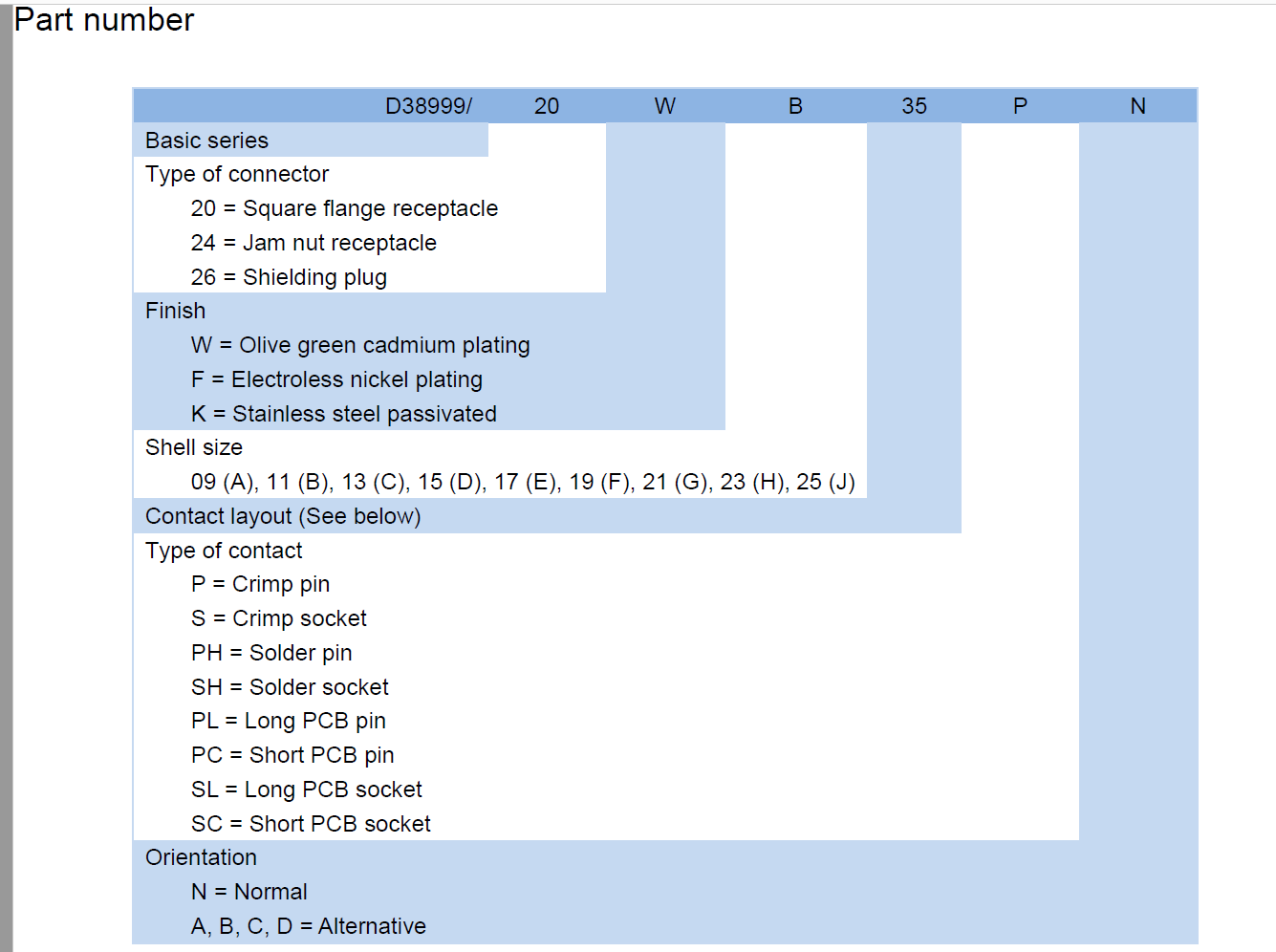
Read top to bottom, the part number is a build instruction as much as a description — the sequence our 38999 connector factory works to when the plug is assembled.
| Position | Code | Meaning |
| Basic series | D38999 | MIL-DTL-38999 Series III |
| Connector type | 26 | Shielding plug, the cable half (20 = square flange receptacle, 24 = jam nut receptacle) |
| Finish | W | Olive green cadmium plating (F = electroless nickel, K = passivated stainless steel) |
| Shell size | B | Size 11; the ladder runs 09 (A) through 25 (J) |
| Contact layout | 35 | The insert arrangement, which must match on the mating half |
| Contact type | S | Crimp socket (P = crimp pin; solder and PCB-tail contacts carry their own letters) |
| Orientation | C | Alternative keying position (N = normal) |
Critical Applications
- Armoured vehicles and mobile command posts. The plug joins hull wiring looms to turret and roof equipment, so a subassembly can be pulled for service without cutting into the loom.
- Missile guidance and radar cabinets. Short, dense signal runs where the interface has to hold between scheduled inspections rather than be re-checked before every task.
- Portable field communications. Cables are coiled, stowed and re-mated daily in whatever weather the unit is working in, so the plug is built as a waterproof military circular connector and the coupling and keying take that wear instead of the contacts.
- Unmanned aerial vehicles and satellite subsystems. A size 11 shell keeps a multi-contact interface inside tight cable routing, and the crimp contacts survive the handling that comes before launch.
- Oil and gas exploration sensors. Instruments are installed once and then left to sit in salt air, where a re-termination in the field costs far more than the connector — the kind of installation a salt spray resistant connector is specified for.
- Emergency response and medical life-support equipment. Repeated connect and disconnect between uses, where a partial mate has to be impossible rather than merely unlikely.
- On an aircraft or a defense platform the plug rarely sits where it is easy to reach. It is the break point at an avionics bay bulkhead, at the junction between an equipment rack and the airframe loom, at an engine control unit, at a flight data recorder, or on the cable that runs out to a sensor or an antenna, and it is often mated one-handed in a space where the technician can feel the keyway but cannot see it. A keyed size 11 shell with a knurled coupling ring suits exactly those positions: it can be aligned by feel, turned until it seats and checked afterwards without tools. The same interface appears on the ground side. Test benches, ground support equipment and flight-line adapters are wired to the Series III receptacle pattern, so one aerospace circular connector plug socket interface serves both the platform and the bench, and a wiring loom pulled from the aircraft can be checked without hunting for an adapter. Loom practice matters as much as the connector. A service loop at the plug keeps the cable from loading the coupling, and a clamp or boot a short distance behind the shell takes the strain that would otherwise reach the contacts. Where a run crosses a pressure bulkhead or a hot zone, tell us the routing and we will confirm the finish and sealing that suit it. Teams that maintain both the platform and its test gear usually standardise on one military circular connector supplier for plug and receptacle, so a replacement drawn from stores always matches what is on the aircraft.
Harsh Industrial & Outdoor Control Systems
- Outdoor control cabinets. The receptacle is mounted through the enclosure wall and the plug stays on the field cable, so a cabinet can be opened and a module pulled without disturbing the wiring inside. A sealed interface is what keeps that joint usable through a wet season, and a cabinet that has to be opened in the rain is exactly where a waterproof military circular connector earns its keep.
- Dockside and marine-adjacent equipment. Mounting height and a drip loop matter as much as the finish; a salt spray resistant connector handles the salt air, but standing water is a routing problem, so keep the coupling below the cable entry where the design allows and let water run off the cable instead of into the joint.
- Transport and mobile machinery. Trailers, lift equipment and temporary installations are mated and unmated far more often than fixed plant, and the thread and keying absorb that wear rather than the contacts.
- Process skids and pump controls. Instruments are wired at the skid and re-connected on site, and a plug that one fitter can re-mate shortens commissioning.
- Mining and heavy machinery. Where cables are expected to be damaged, the plug is the half to keep in store, because it is the half that comes off without opening the equipment.
- Panel builders and integrators. The receptacle goes on the panel and the plug on the cable; standardising on this shell keeps one keying convention and one mating pattern across a build, and ordering both halves from the same 39999 connector factory keeps finish and keying matched.
Program Use Scenarios
- Cable assembly build. The plug is crimped, contact-checked and tested on the bench as part of a finished loom, then delivered to the line with the receptacle already mounted on the equipment.
- Line installation. The cable assembly is routed, the plug is mated last, and the coupling is turned by hand until it seats — no torque wrench and no separate locking wire.
- Scheduled inspection. At each maintenance interval the technician checks the coupling for a fully seated ring and the seal for cuts or grit, and re-mates if the cable has been disturbed.
- Field replacement. When a cable is crushed or a contact is pulled out, the plug is replaced and the receptacle on the equipment is left in place, so the repair does not disturb the equipment side.
- Depot re-termination. Contacts are extracted, a new contact is crimped and inserted, and the plug goes back into service without replacing the whole cable assembly.
- Spares holding. Maintenance teams keep one plug per cable assembly type on the shelf so a repair is not held up waiting for a part — a policy that is only as good as the military circular connector supplier behind it.
Ordering & Delivery
- Start from the part number. Confirm shell size B (11), contact layout 35, crimp socket contacts and orientation C against your drawing and against the receptacle you are mating to — the keying position is the item most often missed.
- Say what has to arrive with it. Tell us whether the assembly needs contacts, backshells or sealing accessories alongside the plug, so the order matches the build rather than the catalogue line.
- Set the quantity. We work to Flexible MOQs, so state what the build actually needs; a repair quantity is as valid a starting point as a production release.
- Ask for the quotation. Payment terms and the production lead time for your quantity are confirmed at quotation, because both depend on the item and the run.
- Agree the paperwork. Tell us at quotation which test records, material declarations or traceability documents your quality team needs to receive; as a mil-dtl-38999 connector manufacturer we can confirm what is available for this order.
- Plan the delivery. Stable global delivery keeps parts moving to your site, with the shipping method and consignee details agreed with your sales contact before dispatch.
Technical Support & Model Matching
Selecting the right connector is rarely a one-line decision. Send us your drawing, part number or a sample, and our engineering team will confirm the matching shell size, contact arrangement, coupling and mounting style, cross-reference discontinued or alternate part numbers, and advise on sealing and flange options for your environment. We also help troubleshoot fit, mating and signal problems, and give installation and commissioning guidance so your line stays up. As a direct manufacturer, our answers come from the people who build the parts — from first enquiry through after-sales support.
FAQ
What is this connector designed for?
It is the cable half of a MIL-DTL-38999 Series III coupling, used wherever a cable assembly has to be joined to equipment and then separated again for service. Power and signal circuits both pass through the same shell, so one plug carries the whole interface instead of several smaller connectors. The thread and keying are there to keep the halves seated, which is why it is specified as a vibration resistant 39999 connector on moving platforms.
Can it be used in harsh operating environments?
Yes — salt spray, moisture, heat and shock are the four conditions this plug is chosen to survive. The shell is aluminium alloy with cadmium plating for corrosion, the interface seal closes when the coupling is seated, and the insert and contacts are built to hold their performance through temperature swings and impact. If your installation adds a particular chemical or a cleaning regime, tell us and we will confirm what the seal and plating can take.
Which receptacle half does this plug mate with?
A receptacle of the same shell size, the same 35 contact layout and the same C keying, with pin contacts to take the sockets in the plug. In practice that is the square-flange (20) or jam-nut (24) body in a matching finish, mounted on the equipment. Because we build both halves as a mil-dtl-38999 connector manufacturer, we can check the keying and layout against each other before the order is released — send the receptacle part number with your enquiry and we will confirm the pair.
Is it suitable for aerospace plug-and-socket integration?
Yes. The plug follows the Series III shell and coupling geometry, so it joins an aerospace circular connector plug socket pair the same way as any other body in the series: it is the cable side, and the receptacle stays on the equipment. Before you commit, check the mounting envelope on the equipment, the keying position and the contact layout against the existing interface — those three decide whether the halves mate.
What does the C in the part number mean for installation?
It is the orientation, or keying, position. The D38999 26WH35SC connector is built in orientation C, one of the alternative positions in the series, where N would be normal. Keying stops two circuits of the same shell and layout being cross-connected by accident. The receptacle has to be keyed the same way — a C plug will not fully seat on an N receptacle — so quote the keying letter together with shell size and layout when you order the mating half.
Can the same shell be supplied with other contacts or finishes?
The part-number scheme covers the options. The finish letter runs W for olive green cadmium, F for electroless nickel and K for passivated stainless steel. The contact letter runs P for crimp pin and S for crimp socket, with solder and PCB-tail contacts carrying their own letters. Orientation can be normal or one of four alternatives. Tell us the letter combination your drawing already uses and we will confirm it against the shell and insert you need.