Product Overview
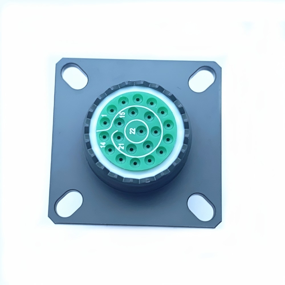
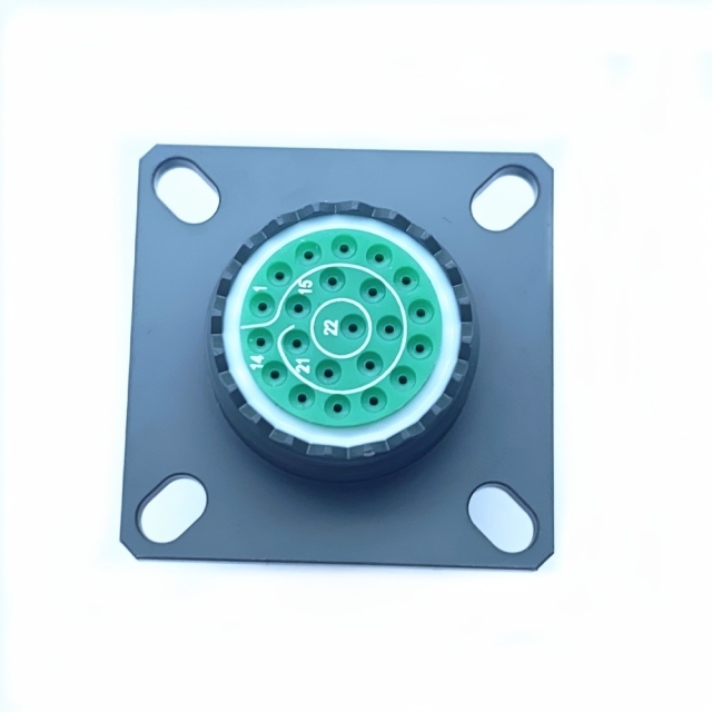
A square flange receptacle from the MIL-DTL-38999 Series III range, made for panels, bulkheads and equipment boxes that sit in salt air rather than in a clean cabinet. Four corner holes hold the flange flat against a cut-out with the insert facing outward, so this is the panel-side half of a plug-and-receptacle pair — the half that stays bolted down while the cable end plugs in and out for test or maintenance. As a D38999 Series III connector it uses the standard shell dimensions, coupling thread and contact layouts of the series, which means the plugs, backshells and crimp tooling already in use on that interface still apply.
Contacts are crimp sockets, the female side of the interface, so a mating plug fitted with pin contacts completes the circuit. They sit in a green insulator with the contact openings visible under the protective cover, and the keying is machined into the insert so a plug can only be offered up one way. The square flange spreads clamping load across the panel instead of concentrating it on a threaded collar — the reason this body style is chosen wherever a receptacle is mounted once and then left alone for years.
Every unit is assembled and plated by a MIL-DTL-38999 connector manufacturer working to the published Series III drawings, and the same line supplies the mating plugs, contacts and rear accessories needed to complete a cable assembly. On a shipboard refit that matters: the receptacle, the plug and the spares can come from one D38999 circular connector supplier rather than three.
Salt-Spray & Marine Performance
Salt is the slowest and most reliable destroyer of a deck-level connector. Spray settles on the flange, dries, and leaves a chloride film that attacks exposed metal; the cadmium finish on this shell is what holds that film back. On a marine circular connector the first corrosion usually appears at the flange screws and the coupling thread rather than at the contacts, which is why the plating matters as much as the insert inside it. Moisture arrives from two directions — driven spray outside, condensation inside when a warm enclosure cools overnight. The mating face closes against a resilient seal, and the rear accessories you choose are what finish the seal at the cable end. Marine refits rarely fail on the receptacle itself; they fail on the second item — the mating plug, the backshell or the contacts — arriving in a different finish or a different shell size.
Coupling & Panel Installation
- Check the panel cut-out before drilling. This D38999 Series III connector uses the standard four-hole square flange, and it is the insert clearance rather than the hole spacing that decides whether the body seats flat against the panel.
- Crimp the socket contacts with the matched tool and load them from the rear in the positions shown on the layout drawing. Push each one home until it clicks into the retention clip — a partly seated contact backs out on mating and takes the circuit with it.
- Bolt the receptacle to the panel with the insert facing out, tightening the corner screws evenly. A warped flange lifts the mating face and the seal no longer closes squarely.
- Line the plug keyway up with the key in the insert; the N mark at the centre of the insert is the normal orientation. Offer the plug up straight, because keyed inserts are unforgiving when they are cross-threaded.
- Turn the coupling ring. This threaded coupling military connector uses a triple-start thread, so the plug picks up within a fraction of a turn and then draws down progressively. Hand-tight is enough, and the ring should seat with no visible gap at the flange.
- Inspect after mating: full thread engagement, no gap at the interface, no rocking when the cable is flexed. If the ring will not seat by hand, stop — a cross-threaded coupling ring is a repair, not a tightening problem.
Critical Applications
- Shipboard power and control panels: deck distribution boxes, engine-room junction boxes and pump controls, where the receptacle is bolted to a steel enclosure and the cable is unplugged for maintenance.
- Deck washdown and weather-exposed junctions: this waterproof military circular connector is specified where hoses, spray and standing water are part of the working day rather than an exception.
- Offshore platform instrumentation: pressure, level and flow sensor runs on wet decks, using this marine circular connector where condensation forms inside an enclosure overnight.
- Bridge and navigation electronics: radar, heading and communications racks that have to keep working through spray and the salt haze that settles on everything above the waterline.
- Avionics bays and engine control units: the same interface runs through our aerospace circular connector range, so airborne looms and ground test boxes can share one plug type.
- UAV and satellite subsystem harnesses: keyed, compact connections that must not work loose under launch vibration or thermal cycling.
- Armoured vehicles and ground systems: bulkhead penetrations for communications, sensor and power runs that see shock, mud and pressure washing.
- High-reliability industrial duty: oil and gas exploration sensors, emergency response equipment and medical life-support devices, where a connector failure is an incident rather than a maintenance item.
Specifications
| Attribute | Value |
| Mating interface | MIL-DTL-38999 Series III (D38999) |
| Shell material | Lightweight, corrosion-resistant aluminium alloy |
| Contact material | Gold-plated copper alloy |
| Voltage rating | 1,500 V AC RMS |
| Current rating | Up to 5 A per signal contact; up to 23 A per power contact |
| Operating temperature | -65 °C to +200 °C |
| Ingress protection | IP67/IP68 sealing |
| Shock | High-shock duty as required by the series |
| Corrosion | Salt fog and chemical atmospheres |
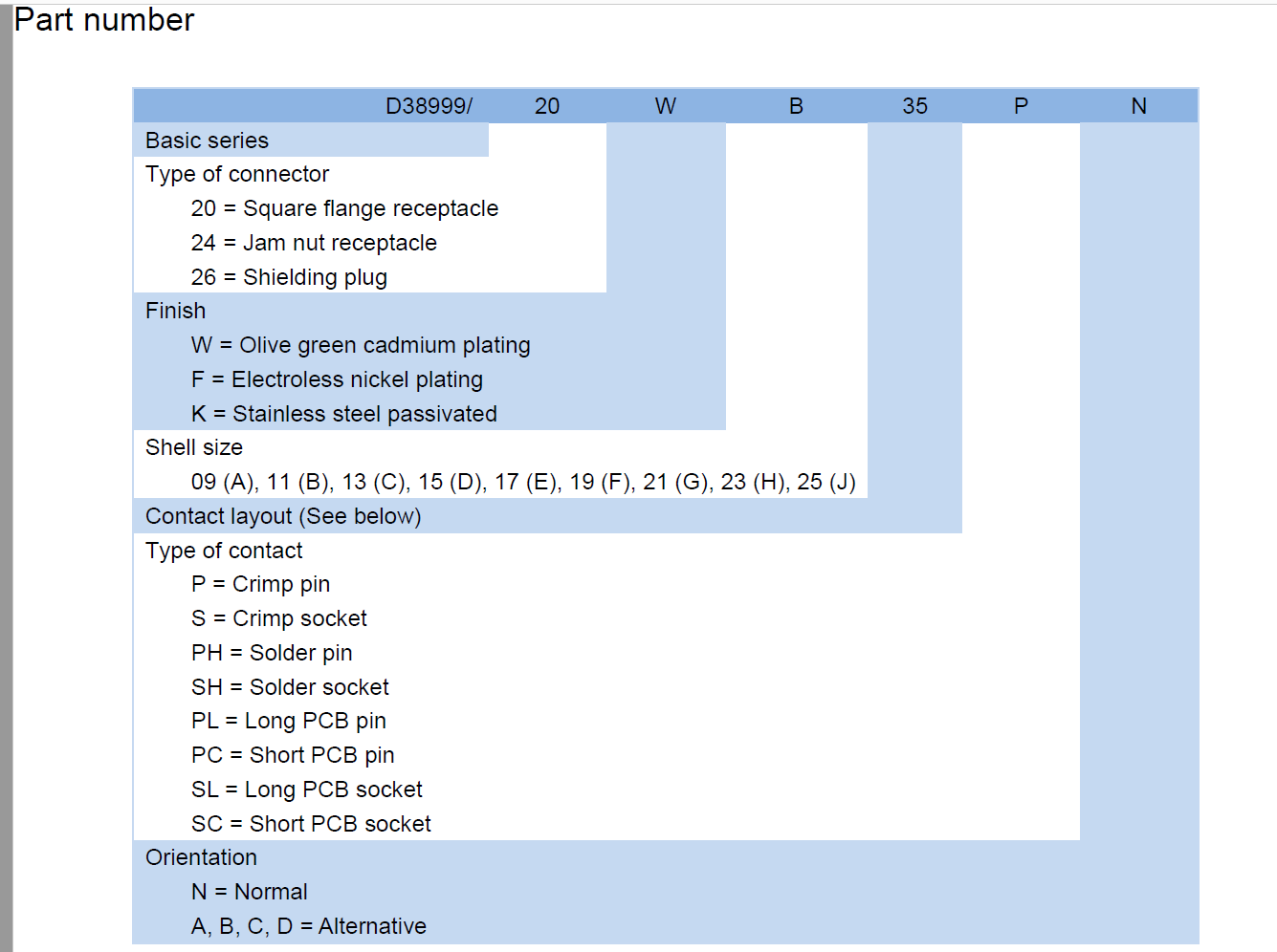
Part Number Breakdown
| Code | Meaning |
| Basic series | D38999, MIL-DTL-38999 |
| Connector type | 20 — square flange receptacle |
| Finish | W — olive green cadmium plating |
| Shell size | C — shell size 13 |
| Contact layout | 35 — layout 35 |
| Contact type | S — crimp socket |
| Orientation | N — normal keying |
| Mounting | Panel mount, four corner flange holes |
| Full reference | D38999 20WC35SN |
Ordering & Delivery
- Send the part number exactly as it appears on the old label, or a photograph of the connector and its shell markings. We cross-reference it against the MIL-DTL-38999 range and confirm shell size, contact layout and finish before quoting.
- Confirm the mating half. This is a threaded coupling military connector, so the plug must carry the matching triple-start thread and shell size; a bayonet plug from another series will not do.
- Confirm the contact arrangement for your layout against the drawing, and say whether crimp sockets should ship with the receptacle or be ordered separately for the wiring assembly.
- Agree quantity, packing and shipping terms with your sales contact. As a D38999 circular connector supplier we confirm minimum order quantity, current lead time and freight at quotation for the quantity and destination you need.
- Round out the order with the mating plug, contacts and rear accessories from one military circular connector supplier. Not every item in the range is listed in our catalogue, so if a shell size or contact layout is missing from it, ask — it is usually a question of matching the code rather than a different product.
Technical Support & Model Matching
Choosing the right shell size, contact arrangement, keying and coupling for a cable assembly is where most ordering problems start, so our engineers work through it with you before anything is shipped. Send a part number, drawing or photo of the connector you are replacing and we will cross-reference it against our MIL-DTL-38999 range and confirm the closest equivalent. After delivery we stay available for mating and installation guidance, wiring questions and fault finding, and we are glad to quote bulk orders and custom designs.
- Made, plated and inspected in one plant. As a MIL-DTL-38999 connector manufacturer we keep shell machining, cadmium plating and contact loading on the same site, so a drawing change reaches the part without a chain of suppliers in between.
- Direct supply, no middle layer. Buying from a D38999 circular connector supplier that builds the part means the person answering a technical question is looking at the same shop floor as the person making it.
- One military circular connector supplier for the whole cable assembly. Plugs, receptacles, crimp contacts and rear accessories come from the same range, so a mating plug ordered six months later still matches the receptacle already bolted into the panel.
- Interface continuity across programmes. The same body styles and contact system run through our aerospace circular connector range, so a cable assembly shop building both airborne looms and marine panels keeps one set of crimp tools and one set of procedures.
- Sealing and shock checks on every production run, not on a sample pulled once. Each unit is inspected against the series requirements, and the documentation travels with the run it came from, so receiving inspection has something to check against.
- Support while the part is still being specified. Layout, keying, finish and mating questions are less costly to settle before the batch is built and far more expensive to find out afterwards.
Between-Refit Maintenance
- Tie the inspection to the refit schedule instead of waiting for a fault. Every time the cable is unmated for test, docking or a panel change, take the opportunity to unmate fully, look at the interface and remate deliberately. A connector that is never opened is never checked.
- Start at the contact faces. Bright gold on the socket and pin faces means the plating is intact; a dull, pitted or discoloured face means arcing or fretting has already begun, and that contact should be replaced rather than polished back into service.
- Check the coupling thread and the four flange screws before you look at the insert. On a marine circular connector these are where corrosion shows up first — a white bloom on the cadmium finish, a thread that turns stiffly, or a screw that will not draw down all point to the same thing: the shell needs attention before the next deployment.
- Wipe the thread with a dry, lint-free cloth and reseat the coupling ring by hand. Do not pack grease into the thread or the interface seal unless the drawing calls for it; a greased seal collects grit and holds it against the elastomer, which is worse than dry.
- Inspect the interface seal and the rear accessories as one item. A seal that is nicked, flattened or carrying grit will pass a bench check and still leak on deck, and a backshell or gland that has loosened off the cable jacket gives moisture a path straight to the contacts.
- Keep a spares kit sized to the installation: several spare crimp sockets in the layouts you actually use, one spare mating plug, a spare interface seal and the contact extraction tool. Because the contacts are crimped rather than soldered, a damaged one is swapped out on the bench instead of reworked in place, and the tool is what makes that possible.
- Store unmated connectors with the protective cap on, contacts shielded, in a dry cabinet away from solvent vapour. A receptacle carried loose in a toolbox is where bent sockets and distorted keys come from, and a distorted key will not mate cleanly again.
- Label every spare with shell size, finish code and contact layout. Mixing a W-finish receptacle with an F-finish plug on the same panel sets up a corrosion cell at the interface, and that kind of mismatch is easy to create accidentally when parts are kept loose in a stores bin.
FAQ
Will this receptacle mate with the Series III plug already on my wiring?
On the interface, yes. Shell dimensions, keying and the coupling thread follow MIL-DTL-38999 Series III, and that standardised geometry is exactly why this D38999 Series III connector drops into existing assemblies instead of forcing a redesign. Check three things against your plug: shell size, contact layout and pin-versus-socket.
A Series III plug from another maker should mate for the same reason — the interface is published rather than proprietary, and the same holds across our aerospace circular connector range. When mating does fail on site, it is nearly always a mismatched shell size or a bayonet plug offered up to a threaded receptacle.
How does the triple-start thread behave under vibration?
Better than a bayonet in most panel installations, which is why the threaded coupling military connector became the default for Series III. Three interlocking thread starts draw the plug down evenly and hold a preload on the coupling ring, so vibration has to overcome friction along the whole thread rather than flick a single lug out of its detent. The ring stays seated on engine-driven equipment, vehicle bulkheads and airborne mounts without lockwire.
The field failure to watch for is under-tightening, not back-off. A ring left a quarter turn short looks mated and is not; seat it by hand and check for a gap at the flange.
Can it be used on deck and in offshore spray?
Yes — that is the duty this part was chosen for. Shipboard, offshore and other marine circular connector installations keep the receptacle in salt-laden air, and the plated aluminium shell is there to keep the flange and coupling thread serviceable through it.
Mated and properly dressed into a backshell, this waterproof military circular connector is sealed to IP67/IP68, which covers washdown and driven spray. What it cannot do is compensate for a missing rear accessory or a cable gland left loose, so inspect the flange screws and the coupling thread at each refit — those are the first places corrosion shows.
Do you build to the MIL-DTL-38999 Series III interface, or is this a proprietary pattern?
To the published interface. Shell dimensions, keying, contact layouts and the coupling thread follow MIL-DTL-38999 Series III, which is what makes the part usable as a replacement in an assembly designed around a D38999 drawing. As a MIL-DTL-38999 connector manufacturer we build from those drawings rather than from a house pattern.
If your programme needs a specific qualification document or a first-article report before the part can be released, say so at enquiry and we will confirm what can travel with the order.
Which finish should I specify if the drawing does not call for W?
W is the code on this receptacle, and it is the cadmium option in the series — the finish traditionally called for on shipboard and offshore work. The same series also runs F (electroless nickel plating) and K (stainless steel passivated), and which one is right depends on the surrounding hardware and on what your corrosion-control document requires.
Send the drawing or the old label and we will confirm which finishes the shell size and contact layout are available in before you commit to a batch.
What maintenance do the contacts and seals need between refits?
Very little beyond inspection, but the inspection has to actually happen. Unmate the plug, check for a bright face on the contacts, look for moisture or a white bloom around the insert, and wipe the coupling thread before remating. Do not pack the interface with grease unless the drawing calls for it — a greased seal collects grit and holds it against the elastomer.
Contacts are crimped rather than soldered, so a damaged one is replaced instead of reworked. Keeping a few spare crimp sockets and a spare mating plug with the tooling turns a stoppage into an afternoon's work.