Product Overview
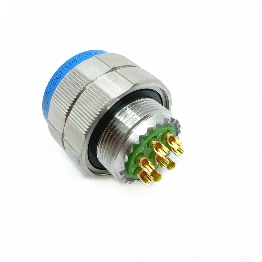
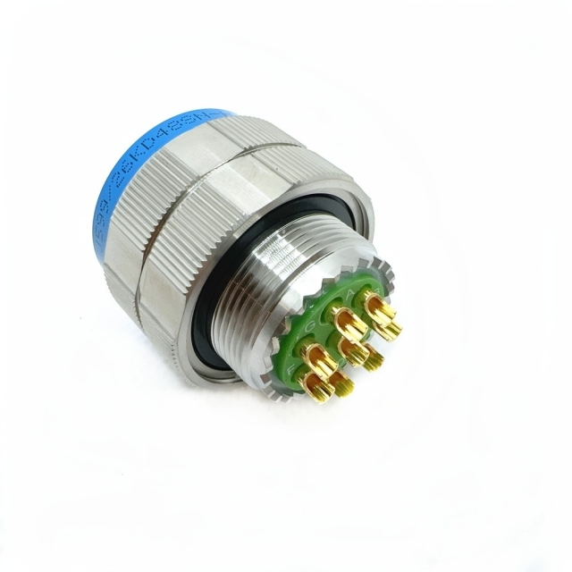
This is a MIL-DTL-38999 Series III connector of the shielding-plug type: a stainless steel shell carrying crimp socket contacts, built to mate with a receptacle on the equipment side. The coupling is a thread rather than a bayonet twist, and that single detail decides where this threaded coupling military connector belongs — it is the version specified for mounts that keep moving rather than panels that are set once and left alone.
On a vehicle or an airframe the plug is the cable half of the pair. It threads onto a panel mount military circular connector at the bulkhead — the square-flange or jam-nut receptacle the cable bundle runs into — and the coupling ring draws the two shells together until they seat on the shoulder. Everything the installer touches sits on the outside: the knurled coupling ring, the keyway that prevents a wrong-orientation engagement, and the rear of the shell where the backshell and cable clamp are fitted.
Orders usually come from cable assembly shops, vehicle builders and repair depots, and they fall into two groups. New-build orders want a sealed, shielded plug for a cable run that has to live with dust, spray and constant movement. Replacement orders want the same interface as the plug coming off, so the receptacle and the loom stay untouched. As a D38999 connector supplier we build both to the same interface, which keeps this plug backward compatible with legacy Series III assemblies rather than tying it to one programme.
Threaded Coupling & Vibration Behaviour
- Three thread starts, short engagement. The coupling advances three thread starts per turn, so the plug runs down in a fraction of the turns a single-start thread would need — worth having when the technician is working in a wheel arch or behind an avionics rack with one hand free.
- The thread resists back-off. Once the ring is seated, vibration has to unwind the full engaged length before the two halves can separate. That is why a threaded coupling military connector is the usual choice for engine-side, transmission-side and airborne mounts, where a quarter-turn bayonet can walk loose over a service life.
- Seating is a feel, not a guess. The coupling ring bottoms out at the shell shoulder. A plug left half a turn short still passes a continuity check and still looks mated, but the seal is not compressed and the first pressure or vibration cycle will show it.
- Shield continuity runs through the coupling. On a shielding plug the cable screen terminates at the shell and the coupling carries that path into the receptacle. That continuous shell-to-shell contact is the difference between a ruggedized aerospace connector and a general-purpose circular one.
- Inspection starts at the ring, not the contacts. The wear items on a threaded plug are the coupling ring, the thread and the keyway; a D38999 connector supplier sees far more damage there than at the contact interface, and a look at each service interval catches most of it before it becomes a wiring failure.
Mounting & Mating Checklist
- Confirm the mating half. Check that the panel mount military circular connector on the equipment is the same shell size and layout, and that its keying corresponds to the plug's normal orientation.
- Dry-fit before the cable is dressed. Offer this MIL-DTL-38999 Series III connector up to the receptacle by hand — if the keyway will not engage without force, the shell size, layout or keying is wrong, and turning harder only damages both halves.
- Start the thread by hand. Turn the knurled ring clockwise until it catches, then run it down by hand. It should feel smooth and should not rock on the shell.
- Seat to the shoulder. Turn until the coupling ring bottoms out, then check that the gap between the two shells is even all the way round; an uneven gap means the plug is cocked on the thread.
- Clamp the cable before the wiring is tied down. Support the cable so its weight and flex load go into the backshell and clamp rather than into the coupling thread.
- Re-check after the first vibration run. Look for fretting dust around the thread, a polished wear mark where the ring has been moving, or a loosened cable clamp.
- Mark the fitted part on the wiring drawing. Shell size, layout and contact type on the drawing turn the next replacement into a one-step order instead of a measuring job, whether the next order is a single plug or a military circular connector wholesale batch.
Field Repair & Rear Sealing
- The plug is sealed at the mating face only. The seal sits at the shell shoulder where the coupling ring draws the plug down onto the receptacle; everything behind the insert stays open until the back of the shell is closed off. Moisture entering at the rear travels along the wire bundle to the contact cavities, which is where corrosion and cross-position faults actually start.
- A backshell closes the cable entry. A straight or angled backshell sized to shell size 15 and to the cable jacket gives the assembly its strain relief, its screen termination point and its rear seal; a boot or a heat-shrink breakout does the same job on lighter cable where a full backshell is not needed.
- Sealing and screening are separate decisions. On a shielded run the rear accessory has to do both — clamp the screen to the shell for shield continuity and seal the jacket entry against spray and washdown. One without the other leaves a ruggedized aerospace connector that is either electrically noisy or wet inside.
- Contacts extract from the rear face. Each crimp socket is held in a numbered cavity by a retention clip, and the matching extraction tool releases the clip so the contact and its wire come back out through the grommet without disturbing the neighbouring circuits.
- Re-terminate rather than re-use. Cut back to clean wire, crimp a new gold-plated socket at the correct strip length, check the pull, and insert until it seats. A socket that has been re-formed or re-soldered in place rarely survives the next vibration cycle.
- Keep a small spares kit at the bench. Spare sockets in the wire sizes the cable assembly uses, an insertion and extraction tool for that contact size and the right crimp die turn a damaged position into a short repair instead of a plug change.
- If a new contact will not lock, the insert is the problem. A cavity that refuses a correctly crimped socket, or a wire that pulls free with the clip still in place, means a damaged insert or retention clip; the plug then comes off the cable assembly for inspection rather than going back into service as a D38999 26KD48SN connector with doubtful retention.
- Settle the rear termination at drawing stage. Straight or angled, screen termination style, clamp range and whether a boot or a backshell is used are far easier to fix on the assembly drawing than at the bench, and they carry forward onto the next build.
Critical Applications
- Armoured and tactical vehicles. Cable runs crossing the hull, the turret ring or a suspension mount are where shock and sustained vibration do the damage; the plug is the break point, so a damaged run is split and replaced without pulling the whole loom.
- Airborne systems and avionics bays. Engine control units, flight data recorders and bay wiring all need an interface that holds through pressure cycling and temperature swing, which is why this is specified as a ruggedized aerospace connector rather than an industrial one.
- Bulkhead and enclosure entries. Where a cable crosses a hull wall or equipment shelter, the run terminates in a panel mount military circular connector and the plug on the outside takes the spray, dust and washdown the panel never sees.
- UAV and satellite subsystems. Contact density and weight both count here; the shielding plug body keeps the screen path short and the sealed interface survives the vibration of launch and recovery.
- Missile guidance, radar and portable field equipment. Short runs, high channel counts and equipment that is carried rather than installed — the plug has to start on its thread in poor light and stay mated afterwards.
- High-reliability industrial. Oil and gas exploration sensors, maritime navigation, emergency response equipment and medical life-support hardware use the same sealed interface where a commercial circular connector would be the weak point.
Specifications
| Series | MIL-DTL-38999 Series III |
| Coupling | Triple-start threaded |
| Contact material | Gold-plated copper alloy |
| Contact rating | 5 A signal / 23 A power |
| Voltage rating | 1,500 V AC RMS |
| Sealing | IP67/IP68 against dust and moisture |
| Operating temperature | -65 °C to +200 °C |
| Vibration | 10–2000 Hz |
| Shock | 100 G |
| Corrosion resistance | Salt fog and chemical atmospheres |
Part-Number Reference
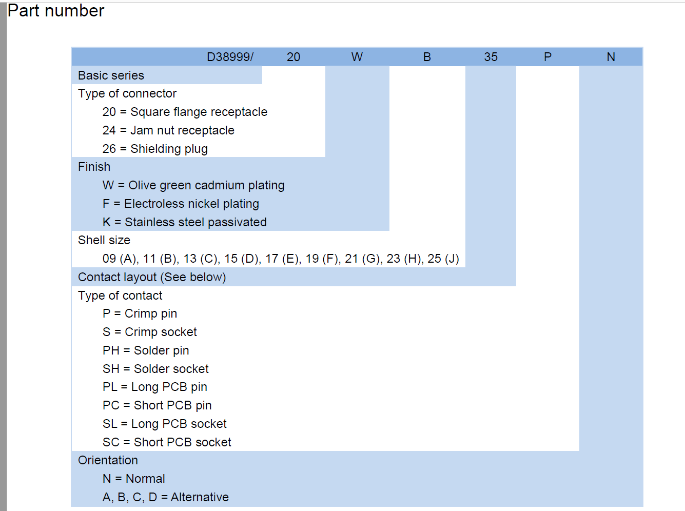
| Designation | D38999 26KD48SN connector |
| Basic series | D38999, MIL-DTL-38999 Series III |
| 26 | Shielding plug |
| 20 / 24 | Square-flange receptacle / jam-nut receptacle |
| K | Stainless steel, passivated |
| W / F | Olive green cadmium plating / electroless nickel plating |
| D | Shell size 15, in a range running from 09 (A) to 25 (J) |
| 48 | Contact layout |
| S | Crimp socket |
| P / PH / SH | Crimp pin / solder pin / solder socket |
| PL / PC / SL / SC | Long and short PCB pin and socket tails |
| N | Normal keying; A, B, C and D are alternates |
Ordering & Delivery
- Send the full part number and quantity. That is enough for a D38999 connector supplier to quote, and you can add shell size, layout or contact type if you already have them broken out.
- Send the receptacle number as well if there is one. If the plug is going onto an existing panel, including that number lets the fit be checked before the order is released.
- Say whether it is a repair or a programme. Military circular connector wholesale quantities are quoted next to single repair parts, and the specification does not change with the order size.
- Ask about samples. Tell your sales contact what the sample has to prove — shell fit, sealing or contact retention — and confirm current availability and terms.
- Confirm lead time for your quantity and schedule. Timing depends on shell size, finish, contact type and what else is running, so the date is quoted per order.
- Agree the commercial terms before release. Payment method and split, Incoterms and destination port are confirmed on the quotation.
- Agree the packing. Bulk cartons, individual bags or kitted sets with backshells are all possible; confirm what your stores or line needs so it is priced into the order.
- Ask for the documentation your receiving inspection needs — test records, lot marking, certificates — and confirm the warranty terms that apply to your order.
Technical Support & Model Matching
Choosing the right shell size, contact arrangement, keying and coupling for a cable assembly is where most ordering problems start, so our engineers work through it with you before anything is shipped. Send a part number, drawing or photo of the connector you are replacing and we will cross-reference it against our MIL-DTL-38999 range and confirm the closest equivalent. After delivery we stay available for mating and installation guidance, wiring questions and fault finding, and we are glad to quote bulk orders and custom designs.
Every unit is built to the MIL-DTL-38999 Series III interface, with the shell, contact and finish work held in-house instead of being bought in per order. As a MIL-DTL-38999 connector manufacturer we run the plating sequence ourselves — nickel under the gold on the contacts, passivation on the stainless shell — because that is where most field failures in this class begin: a contact that pits, or a shell that starts to corrode at the thread. Sealing and coupling are checked on the assembled plug rather than on a sample from the batch, so the thread and keyway are known to seat before the part is packed. That is the difference between a threaded coupling military connector that lasts a vehicle's service life and one that has to be re-terminated after the first season. Buyers placing military circular connector wholesale orders get the same build as a single repair part; nothing is downgraded because the quantity is larger. Support runs past the shipment. The drawing and part number stay with the job, so a repeat order two years later is the same connector rather than a lookalike, and cable assembly shops can send an assembly in for integration instead of buying loose plugs and backshells. Where a programme falls under ITAR or ECCN controls, say so at enquiry stage and the export paperwork is settled before anything is booked for dispatch. If your quality plan calls for a specific approval or an approved-source listing, raise that at the same point — we will tell you exactly what we hold rather than let it surface at receiving inspection.
FAQ
How do I match the D38999 26KD48SN connector to the receptacle already on the panel?
Read the number on the existing receptacle and compare three things: shell size, contact layout and keying. Plug and receptacle have to share shell size and layout, and the orientation code has to correspond — a normal-keyed plug will not seat on an alternative-keyed receptacle. Coupling style settles the rest: a MIL-DTL-38999 Series III connector mates only with a Series III receptacle, so a bayonet receptacle from the Series I or Series II family will not thread onto it.
Can a damaged crimp socket contact be replaced without scrapping the plug?
Usually yes. Crimp socket contacts come out with the correct extraction tool, so a bent or corroded contact can be pulled, a new gold-plated socket crimped onto the wire and re-inserted into the same insert. Give the finished wire a gentle pull to check retention — if the contact moves, the retention clip or the insert is damaged and the plug should come out of service rather than go back into the wiring assembly.
Does the plug seal on its own, or do I need a backshell?
The plug seals at the mating interface; the rear is a separate job. The cable entry needs a backshell and the right rear accessory to be sealed and strain-relieved, and that is what completes the assembly as a ruggedized aerospace connector. Match the backshell to the shell size and to the screening the cable assembly needs, and confirm the accessory part number if your drawing does not already name one.
How does threaded coupling compare with a bayonet military circular connector?
Bayonet coupling is a push-and-quarter-turn and belongs to the Series I and Series II families; Series III uses a triple-start thread, so the plug takes a few more turns to run down. On a crowded panel a bayonet is quicker in and out; on a mount that rarely comes apart in service the extra turns cost nothing and the seating is more positive. The two styles do not interchange, so match whatever is already on the panel.
Can signal and power contacts share one shell?
Yes. The Series III shell accepts mixed contact types, so one insert can carry signal, power, coaxial and high-speed data contacts alongside each other, which is how hybrid layouts are built. What limits the mix is the contact layout and the insert behind it — tell us the circuits you need to run and we will confirm which layout carries them and which socket sizes that layout accepts.