Product Overview
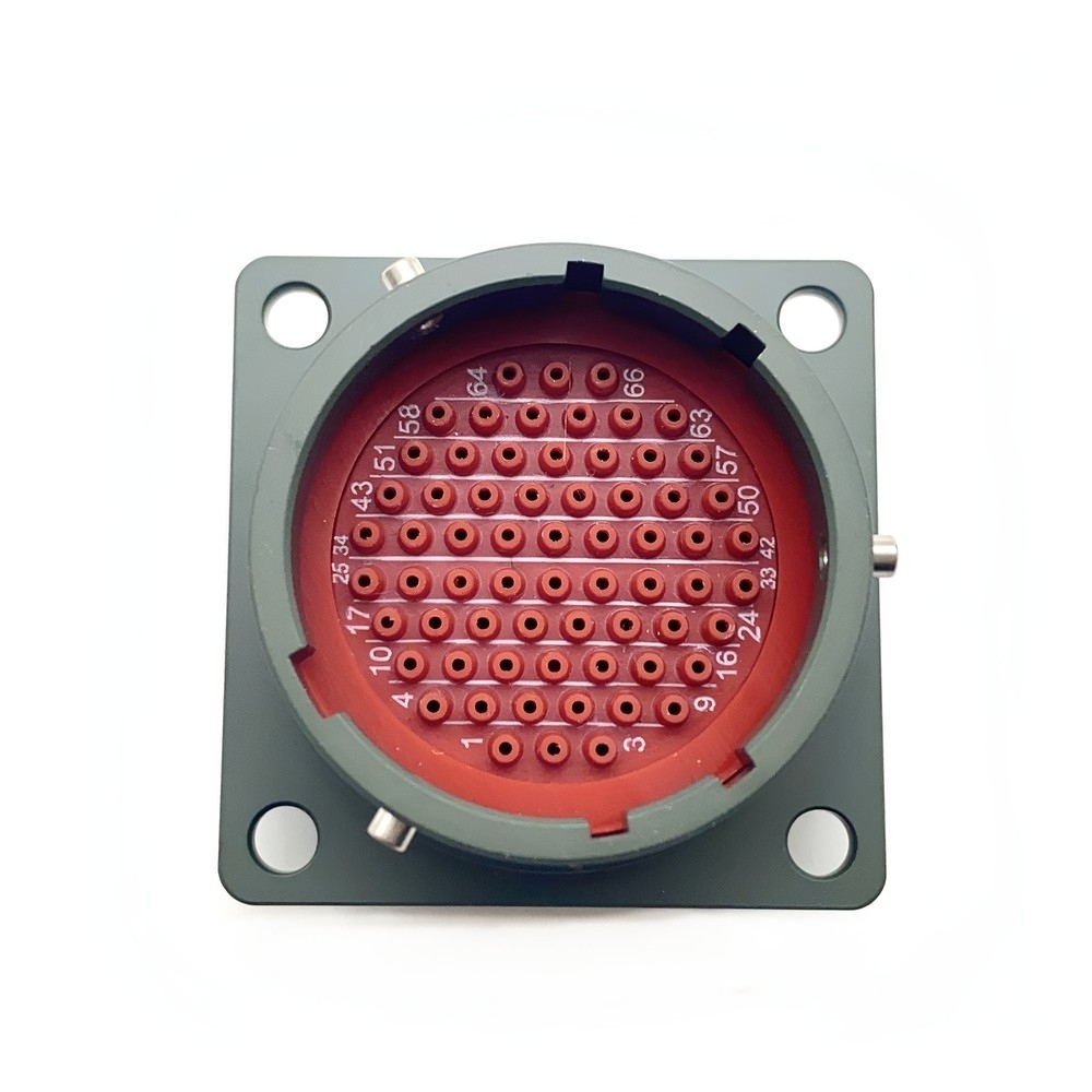
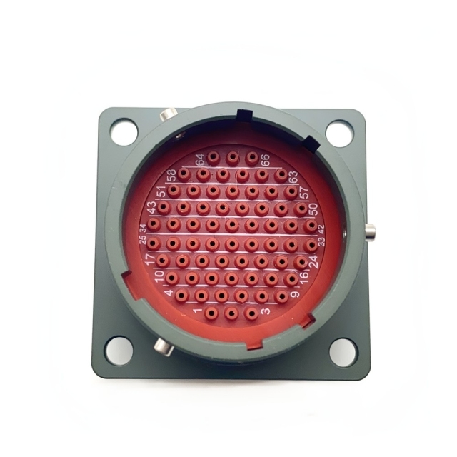
MS27508T18B35PB is the rear-mounting box receptacle of the MIL-DTL-38999 Series II family — an IP67 sealed circular connector that is fixed to a bulkhead or an equipment wall while the plug arrives from the outside. The shell is size 18, the flange is square, and the body mounts from behind the panel, so the fixing screws and the rear accessory stay inside the enclosure while the coupling ring faces the technician. Contacts are crimp pin on the 35 layout, gold plated and carried in a colour-coded insert that keeps circuit identification readable through assembly, ring-out and fault finding.
Mating is by bayonet ring rather than thread: a MIL-DTL-38999 Series II connector separates with a short turn, which is the whole reason it is chosen for crowded panels and line-replaceable units. The same shell ends up on wiring test benches, where a technician may mate and break one connector dozens of times in a shift, and the coupling is expected to take it.
This is not a general-purpose industrial connector, and it is not sold as a cosmetic upgrade. It exists so an assembly that already uses a Series II interface — an existing plug, an approved panel opening, a drawing older than the current engineering team — can keep that interface while the supply route behind it changes. Behind the part sits a factory rather than a warehouse: as a MIL-DTL-38999 connector manufacturer we keep the Series II range on a live production line instead of a stock list, so a code another source calls obsolete can still be built. MIL-DTL-38999 compliance supports reliable performance in life-critical scenarios.
Series II Interface & Coupling
- Bayonet, not threaded. The coupling ring turns a short arc and locks, so the correct description is a bayonet military circular connector rather than a threaded one. Mating takes a fraction of the time a triple-start Series III thread needs, which matters on a bench that cycles cable assemblies all day.
- Shell 18 sits mid-range. Series II box receptacles run from shell 08 up to shell 24. Eighteen gives a stable flange and a dense insert without the footprint of a 22 or 24 shell, and it is the usual step up when a shell 12 layout starts running short of contacts.
- The 27508 body mounts from the rear. On the MS27508T18B35PB connector the flange sits behind the panel and the coupling ring presents at the front. The 27513 code is the front-mounting box receptacle, so a drawing calling for front mounting is a different part number, not a different assembly method.
- T means threaded rear and accessory. The back of the shell takes a backshell, strain relief or heat-shrink boot. Order the E code if you want the same receptacle without thread or rear accessory hardware.
- Continuity with legacy Series II hardware. Mating plugs, backshells and panel openings already in service do not need redesign or re-qualification. That continuity, more than any single rating, is usually why this part number gets specified at all.
- It will not mate a Series III plug. The two series share a family name and nothing at the interface. Check the cable assembly before cross-referencing, because a Series III plug does not enter this shell whatever the shell size says.
- The mating side can ship with it. Plugs, wall and box receptacles, jam-nut receptacles and rear accessories all sit in the same range, so the plug that pairs with this shell can be ordered on the same line — the practical reason buyers settle on one MIL-DTL-38999 connector manufacturer. Traceable manufacturing includes full documentation support such as certificate of conformance and test reports. As a direct manufacturer, we remove middleman markups to provide competitive volume pricing for aerospace and defense procurement. Flexible order quantities and stable global delivery help keep your supply chain on schedule.
Contact System & Termination
- Read the marking first. The MS27508T18B35PB connector accepts crimp pin contacts on the 35 layout, so confirm wire gauge and circuit count against the wiring drawing before anything is crimped.
- Crimp with a calibrated tool. Gold plating keeps contact resistance low and holds corrosion back in damp, salt-laden air; a crushed barrel or a nick through the plating throws both away.
- Insert until the retention clip seats. Push each contact home, then tug it gently. A contact that shifts on the bench will shift in service.
- Respect the keying. The shell is polarized, so a bayonet military circular connector mates one way only. If a mating half will not turn without force, it is the wrong keying position rather than a tight connector — and bending a pin to make it fit turns a five-minute job into a rework order.
- Keep the insert clean and dry. Colour-coded inserts make a circuit easy to trace, but grease or swarf on the insert face degrades the interfacial seal the first time the connector is mated.
- Inspect before the panel closes. No pushed-back contacts, no nicked plating, no strands outside the barrel, no tool marks on the sealing face.
Sealing & Environmental Performance
Sealing on this MIL-DTL-38999 Series II connector happens in three places at once: an interfacial seal where the two halves meet, individual rear wire seals that close around each conductor, and body seals that close the shell itself. Miss any one of the three and the assembly leaks, which is why the rear accessory belongs to the sealing system rather than to the accessories list. Together they make this an IP67 sealed circular connector: dust-tight, and protected against water during temporary immersion. That covers what most vehicle hulls, deck enclosures and wash-down cabinets actually ask for, and it is reached with the connector mated or correctly capped. The operating window runs from -65 °C to +200 °C, wide enough to take in cold soak at altitude and heat soak near an engine or a power converter without a different part number for each extreme. Salt fog exposure is part of the qualification, which is where the cadmium-plated shell and gold-plated contacts earn their place on coastal and shipboard installations. Mechanical resilience is tested rather than assumed: vibration swept from 10 Hz to 2000 Hz, shock to 100 G, and mechanical impact. Electrically the design holds stable impedance, low insertion loss and shell-level EMI shielding, so a noisy wiring run does not become the weak point inside an otherwise well-shielded enclosure. Two field notes. Flame-retardant materials specified to MIL-STD-810 are used in the build, so the connector does not become a fuel path in a fire-exposed installation. And the seal only holds while the rear accessory is fitted correctly — a loose backshell lets water track along the wires past the rear seals, which is the most common way a good IP67 assembly fails a wet test. The connector uses a triple-seal design with environmental seals, rear wire seals, and connector body seals. Fire-resistant materials are compliant with MIL-STD-810 for flame retardancy.
Mounting, Mating & Field Service
- Prepare the panel opening before the receptacle. Cut and deburr the shell 18 opening, check that the surface is flat, and keep primer or paint off the flange face if the shell is doubling as an EMI ground path. A panel mount military connector is only as rigid as the panel it is bolted to.
- Mount from behind. The square flange sits against the inside face and the coupling ring presents at the front. Run the fixing screws down evenly — snug and even beats tight on one side.
- Terminate, then dress the rear. Contacts and rear accessory are far easier to fit with the cable assembly loose than with the receptacle already bolted into a crowded enclosure.
- Mate with a quarter turn. The bayonet ring should lock with light hand pressure and a distinct detent; a bayonet military circular connector that binds is mis-keyed, not stiff.
- Service through the coupling, not the wiring. The quick-disconnect coupling lets a technician separate the cable assembly without touching the panel fixing or the rear seal. That is where the maintenance hours come back, because nothing has to be re-terminated or re-sealed to swap a line-replaceable unit.
- Changing sources? Send the marking on the part you are removing, the drawing or a photo, and we will cross-check it before the first cut is made. Most of the risk in moving to another MIL-DTL-38999 connector manufacturer sits in the panel opening and the keying suffix, and both are settled before an order goes in.
- Cap it when it is open. An unmated receptacle collects grit and moisture, and an IP67 sealed circular connector holds its rating only while it is mated or properly capped.
Applications
| Environment | Typical installations |
| Aerospace | Avionics bays, flight-control runs, engine monitoring, airframe junction boxes |
| Military ground | Radar racks, tactical vehicle wiring, communications shelters, mast harnesses |
| Marine | Submarine systems, naval vessel electronics, deck and below-deck enclosures |
| Industrial | Test rigs, machine-tool enclosures, outdoor instrumentation cabinets |
| UAV and remote platforms | Payload and telemetry harnesses exposed to transport and launch vibration |
| Repair and overhaul | Bench replacement of a failed Series II receptacle on an existing assembly |
Specifications
| Basic series | MS27508 — MIL-DTL-38999 Series II connector, box square receptacle, rear mount |
| Shell size | 18 |
| Coupling | Bayonet, quick disconnect |
| Rear interface | T — threaded shell with rear accessory |
| Shell finish | B — olive green cadmium plating |
| Contact layout | 35 |
| Contact type | P — crimp pin |
| Contact plating | Gold |
| Keying | Suffix as ordered; N marks the normal position |
| Sealing | IP67 |
| Mounting | Square flange, panel mount, rear fixing |
Part-Number Codes & Ordering
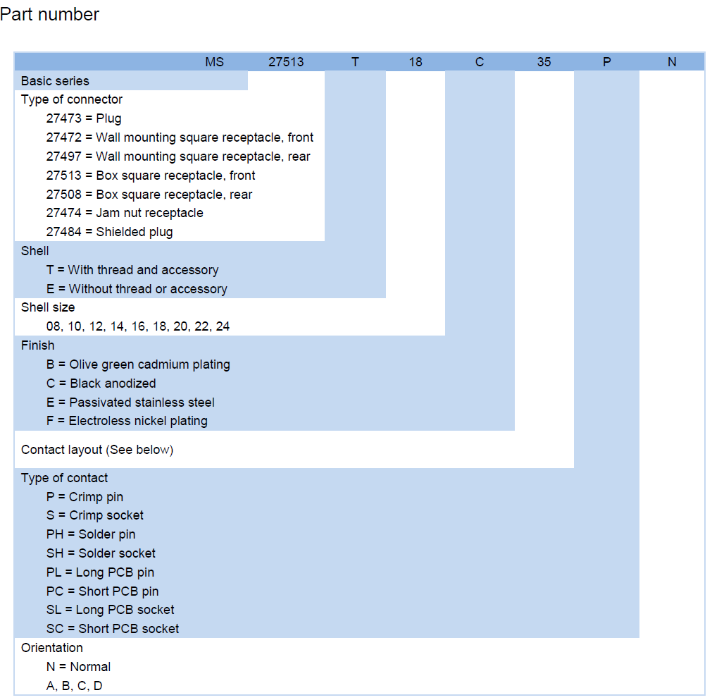
- Read the code left to right. MS27508T18B35PB connector breaks down as 27508 (box square receptacle, rear mount), T (threaded shell with rear accessory), 18 (shell size), B (olive green cadmium plating), 35 (contact layout) and P (crimp pin), with the final letter setting keying.
- T or E decides the backshell. T is the shell with thread and rear accessory; E is the same receptacle without them. That decision is made before anything else is quoted.
- Shell size 18 is one of nine. The family runs 08, 10, 12, 14, 16, 18, 20, 22 and 24, so a design that outgrows its contact count can step up a shell size without changing series or mounting concept.
- Finish codes follow the environment. B is olive green cadmium plating, as supplied here; C is black anodised, E is passivated stainless steel and F is electroless nickel. Read the position in the number as well as the letter, because some letters appear in more than one field.
- Contact type codes. P crimp pin, S crimp socket, PH solder pin, SH solder socket, and PL, PC, SL and SC for long and short PCB tails. A board-mount version therefore keeps the same shell and seal as a cable-assembly version.
- Keying is its own field. The last letter sets the keying position, with N as normal. Two receptacles that look identical can be non-intermateable because of it, so quote the suffix exactly as it appears on the drawing.
- Wall-mounting alternatives. The 27472 and 27497 codes are wall-mounting receptacles, and they are the better answer when a panel mount military connector has to sit on a bracket rather than a machined panel face.
- Custom 38999 circular connectors. A different insert arrangement, a specific finish, private-label marking or a matched plug-and-receptacle kit all go through the drawing rather than the catalogue.
- Documentation you can file. Certificate of conformity and test reports travel with the shipment, so goods-in has something to check the parts against rather than a box and an invoice.
- Built here, answered here. Shell, insert and plating work stay in our own plant, so a repeat order arrives identical to the part that was qualified instead of a version adapted to whatever a subcontractor had in stock.
- Settle these before the order. The keying suffix, whether contacts ship loose or installed, and the rear accessory are worth confirming up front, together with quantity, price, packing and delivery terms, which are quoted per order rather than fixed by the part number. Ask your sales contact for the current position on all of them.
Technical Support & Model Matching
Choosing the right shell size, contact arrangement, keying and coupling for a cable assembly is where most ordering problems start, so our engineers work through it with you before anything is shipped. Send a part number, drawing or photo of the connector you are replacing and we will cross-reference it against our MIL-DTL-38999 range and confirm the closest equivalent. After delivery we stay available for mating and installation guidance, wiring questions and fault finding, and we are glad to quote bulk orders and custom designs.
FAQ
Will this receptacle fit the panel opening I already have?
If the panel was cut for a shell 18 Series II box receptacle, the 27508 body uses the same rear-mount square flange and the same fixing layout. Send the drawing, or a photo of the old mounting face with a rule alongside it, and we will check the opening and the fixing positions against this panel mount military connector before you commit to a batch. A panel cut for a different shell size or a different receptacle type needs a new opening — there is no adapter that makes a shell 12 hole accept a shell 18 flange.
Is it sealed well enough for wash-down or deck exposure?
IP67 is the rating: dust-tight, and protected against temporary immersion. On deck or in a wash-down bay the rating depends on three things — the rear accessory tightened onto the shell, the coupling turned fully to its detent, and the insert face clean and dry. Those same three are the first things to check if a unit ever fails a wet test, and they are why we treat the backshell as part of the sealing system rather than an accessory.
Can I order it with socket contacts, another finish or a different keying?
Yes. The same shell is built with socket contacts, solder contacts and PCB tails, in the C, E and F finishes, and with the keying position set to your drawing. Send the part number you need to match and we will quote custom 38999 circular connectors with the contact type, finish and keying written back on the order confirmation, so there is no ambiguity when the parts reach goods-in.
Is this built to MIL-DTL-38999 Series II?
Yes — shell dimensions, the bayonet interface, the contact system and the environmental test conditions all follow MIL-DTL-38999 Series II, which is what lets the part drop into an assembly designed around that standard. The interface itself is fixed by the specification, so what separates one source from another is the discipline behind it: plating control, contact retention checks and how quickly a drawing question gets answered. Better to answer that question before the order than after the goods-in inspection.
Can I get the mating plug and rear accessories at the same time?
Yes. Plugs, wall and box receptacles, jam-nut receptacles, contacts and rear accessories sit in the same range, so a cable assembly build can be kitted in a single order and the mating plug stays matched to the receptacle. Send the cable assembly drawing and we will list what pairs with shell size 18. Consolidating with one military circular connector supplier is also the simplest way to keep revisions in step — one drawing, one delivery, no mismatched halves at assembly.