Product Overview
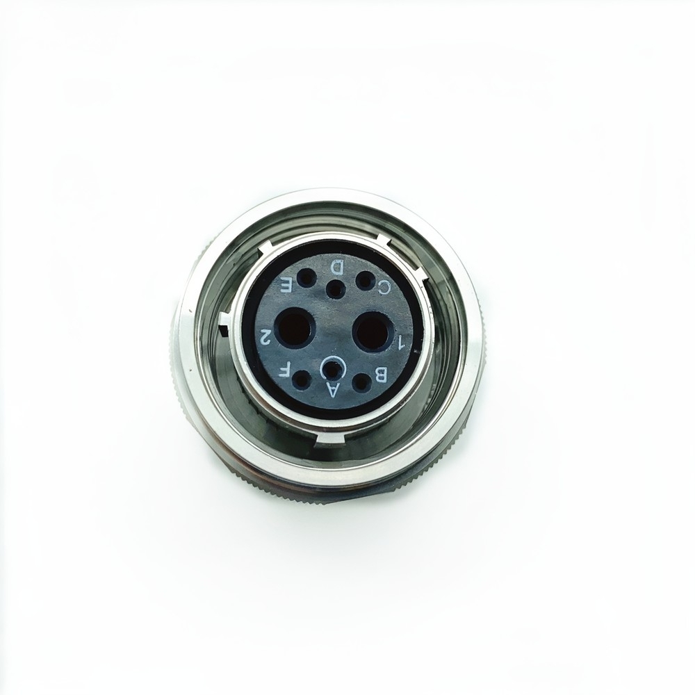
This is the shielded plug of the d38999 series iii connector range: a circular body with a triple-start threaded coupling, a keyed contact insert and crimp socket contacts set to normal orientation. It is the cable-side half of the pair, not a bulkhead receptacle. High shock and high humidity are the two conditions this part is built around, and on a vehicle or an aircraft they usually arrive together. The platform hits the joint with structural shock and constant vibration, then the next cold morning fills the shell with condensation. A sealed shell and a keyed insert keep the contact cavity closed and the contacts square through both. Nothing changes on the bench either — the insert carries labelled positions, so a technician can terminate or ring out against the drawing without counting holes. It suits cable-assembly shops building ground-vehicle and airborne looms, repair depots replacing a failed plug on an assembly that already uses the interface, and integrators who need the interface to stay exactly as it is while everything behind it changes. In light-duty indoor wiring the sealing and the coupling are more than the job needs, and a commercial connector will usually do. Shell, insert, plating and contact loading are specified together before production, which is what lets a mil-dtl-38999 connector supplier keep the interface stable from one batch to the next.
Key Features & Construction
- Triple-start threaded coupling. The ring draws the halves together along three thread starts at once, so engagement is quick and progressive and the joint resists backing off under sustained vibration — the reason a threaded coupling circular connector is specified where a bayonet would be worked loose.
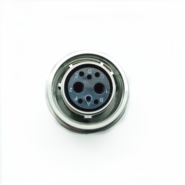
- Keyed insert with labelled positions. Contact positions are marked around the face and the insert only accepts the mating half in one orientation, so termination and inspection follow the drawing instead of guesswork.
- Gold-plated copper alloy contacts. Plating holds contact resistance low and stable through repeated mating and through damp storage, which matters for a part that may sit on a shelf before it is fitted.
- Lightweight, corrosion-resistant shell. The shell carries the mechanical and shielding duty, and the finish code decides how it handles salt fog and chemical exposure over the life of the assembly.
- Mixed contact types in one shell. Signal, power, coaxial and high-speed data contacts can share the same body, so a loom can cross one connector instead of splitting into two separate branches.
- Standard-defined interface. Keying, shell geometry and contact spacing come from the MIL-DTL-38999 Series III standard rather than a single supplier's drawing, so mating parts from different sources stay compatible.
- Sealed mated assembly. The coupling ring covers the interface when engaged and the shell closes the contact cavity against moisture and salt fog in the conditions a rugged military circular connector is built for.
Reading the Part Number
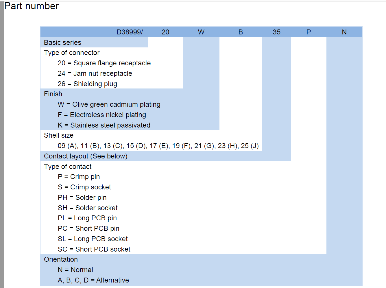
A D38999 number is a specification in itself once you know the order of the fields, and the order never changes: basic series, connector type, finish, shell size, contact layout, contact type, orientation. Connector type comes first in the suffix. 20 is the square flange receptacle, 24 the jam nut receptacle and 26 the shielding plug, which is the body on this part. Finish follows: W is olive green cadmium plating, F is electroless nickel and K is stainless steel passivated — so the K in this number tells you the shell is the passivated stainless option, not the cadmium-plated version that general series notes usually quote. Shell size comes next as a letter, running from 09 up to 25 and lettered A through J with I left out of the sequence. Then the contact layout code, then the contact type: P crimp pin, S crimp socket, PH solder pin, SH solder socket, plus the PCB variants PL, PC, SL and SC for long and short pins and sockets. The last character is orientation — N for normal, A to D for the alternative key positions that physically block a wrong mate. Two characters in this d38999 series iii connector read 26 and mean different things: the first is the body style, the second is the contact layout. That is normal in the scheme, and it is exactly the kind of detail that produces a wrong order when a number is quoted from memory rather than from the drawing. Because the field order is fixed, a d38999 connector manufacturer can cross-check a legacy number field by field — type against type, finish against finish, layout against layout — instead of guessing from a description. What this part gives you over a commodity circular connector is mostly continuity. It holds the MIL-DTL-38999 Series III interface, so a legacy assembly keeps its panel cut-out, its keying and its contact arrangement; the replacement goes in without redesign, without a new wiring drawing and without re-qualifying the mounting. For a repair depot the argument ends there — match the number, fit the part, close the job. The second thing it gives you is a paper trail. Runs can be accompanied by traceability documentation, so receiving inspection can check the shell, finish and contact loading against the purchase order instead of trusting the label. If your programme needs a specific approval or test report, say so with the enquiry; the answer depends on the exact part and the exact standard called out, and it is cheaper to settle before the order than after. Sealing and high-vibration performance are checked against the methods the standard specifies before a run is released, not left to chance at final assembly. That is the part of the process a buyer rarely sees and always pays for later when it is skipped — particularly on a rugged military circular connector that will spend its service life on a moving platform. Defence work tends to bring export-control questions with it. Raise ITAR or ECCN screening early so the classification is settled long before the parts reach a forwarder. The accessories travel with it: backshells, contacts and rear fittings can be quoted on the same order as the plug, so a wiring bench is not held up waiting on a second shipment, and if you would rather take terminated assemblies than loose parts, raise that at the enquiry stage. Send the old number, the drawing or a photo of the failed part, and the cross-reference is usually a short exchange with a mil-dtl-38999 connector supplier that builds the series.
Field Applications
- Armoured and ground vehicles. Cable runs that cross a hull or terminate at a turret junction take repeated shock and long damp spells, which is the duty a rugged military circular connector is chosen for.
- Airborne mounting points. Engine control units, avionics bays and flight data recorders sit where vibration is constant and the shell cycles between ground soak and operating temperature on every sortie.
- UAV and satellite subsystems. Where nothing can be reached for repair mid-mission, the joint is made once at build and expected to hold without further attention.
- Shipboard and offshore equipment. Deck-level moisture and salt fog attack the shell first; the finish code and the sealed interface carry that exposure, and the same body suits navigation and deck machinery.
- Field and portable communications. Radios, manpack sets and vehicle-mounted units are mated and unmated far more often than fixed installations, so this aerospace plug socket connector sees repeated coupling cycles rather than a single build-time mate.
- Bulkhead and panel interfaces. Where the cable meets a panel mount military connector bolted through a bulkhead, the plug carries the moving half of the joint and the fixed receptacle takes the load — so the wear lands on the part that is easier to swap.
- High-reliability industrial equipment. Oil and gas sensors, emergency response gear and medical life-support devices use the same interface where a commercial connector would be the weak point.
Specifications & Ratings
| Interface standard | MIL-DTL-38999 Series III |
| Body style | Shielding plug (connector type code |
| Finish | K — stainless steel passivated |
| Shell | Corrosion-resistant metal shell with keyed contact insert |
| Coupling | Triple-start thread |
| Contact material | Gold-plated copper alloy |
| Contact type | S — crimp socket |
| Contact layout | Set by shell size and layout code; confirmed against the drawing |
| Signal current | Up to 5 A per contact |
| Power current | Up to 23 A per contact |
| Voltage rating | 1,500 V AC RMS |
| Temperature range | -65 °C to +200 °C |
| Sealing | IP67/IP68 |
| Corrosion | Salt fog and chemical exposure resistance per the series |
Mating & Installation
- Inspect both halves before mating — check the insert for bent contacts, the coupling threads for grit and the keyway for damage. A threaded coupling circular connector will still start to thread with a damaged key, and that is how inserts get cracked.
- Check the orientation code against the mating half. N is normal keying; A, B, C and D are alternative positions that physically prevent a wrong mate. If the plug will not start, do not force it — the keys are telling you something.
- Align the keys and push the halves straight together until the threads meet, along the axis rather than at an angle, so the contacts enter the insert square.
- Turn the coupling ring by hand until it seats. Hand effort is enough and the ring should run freely and then stop positively; if your work instruction specifies a torque figure, follow it, and re-check the ring after the first thermal cycle.
- Confirm full engagement before the cable bundle is dressed. The ring should be fully home with no thread visible, and the two halves should not move relative to each other when gently rocked.
- Fit the backshell and strain relief so the cable is carried behind the connector instead of hanging from the contacts. Where the fixed half is a panel mount military connector, leave a service loop on the cable side so the plug is not under tension.
- Break the joint the same way — ring first, straight pull, cap or bag the face if the plug goes back into store. Never unscrew by twisting the cable; on an aerospace plug socket connector the shell takes the load, not the conductors.
Ordering & Confirmation
- Quote the number exactly as it is marked on the old shell, orientation letter included.
- Confirm the shell size and contact layout against the layout chart if you are ordering without a sample. Two numbers that look similar can differ in the insert.
- Say whether you need the aerospace plug socket connector on its own or with contacts, backshell and rear accessories on the same order.
- Confirm the finish code you need — the K passivated stainless shell on this part is one of three codes built on the same body.
- State the quantity and whether this is a one-off repair or a military circular connector wholesale requirement for a build programme, so the enquiry is handled the right way from the start.
- Ask for the documentation package your receiving inspection needs — traceability records, test reports or certificates, whichever your programme calls for.
- Confirm export-control screening if the end use is defence-related.
- Confirm current availability, lead time, packing, marking, shipping terms and volume pricing for scheduled quantities with your sales contact before the order is placed, and ask about sample availability if your engineering team needs to validate the part first.
Technical Support & Model Matching
Choosing the right shell size, contact arrangement, keying and coupling for a cable assembly is where most ordering problems start, so our engineers work through it with you before anything is shipped. Send a part number, drawing or photo of the connector you are replacing and we will cross-reference it against our MIL-DTL-38999 range and confirm the closest equivalent. After delivery we stay available for mating and installation guidance, wiring questions and fault finding, and we are glad to quote bulk orders and custom designs.
FAQ
How does this connector handle shock and humidity together?
The coupling is a three-start thread that draws the halves together progressively and holds them there, so the joint does not work loose the way a bayonet can on a vehicle hull or an engine mount. The shell seals the contact cavity against moisture, and the gold-plated contacts keep resistance stable when damp air does reach the mated area during thermal cycling. For high-humidity sites the practical precaution is on the cable side: a proper backshell and strain relief stop water tracking down the conductors into the insert.
Will it mate with the Series III receptacle already on my wiring loom?
Yes, provided that receptacle is built to the MIL-DTL-38999 Series III interface and matches the shell size and keying. The interface is defined by the standard rather than by a single supplier, which is why a d38999 series iii connector from one maker mates with a receptacle from another. Check the orientation code before you commit — an A, B, C or D key mates only with its matching counterpart, and forcing a mismatched pair is the fastest way to damage an insert.
What does the finish code on this part mean?
The character after the connector type is the finish: W is olive green cadmium plating, F is electroless nickel and K, the code on this part, is stainless steel passivated. K is the passivated stainless shell option, usually chosen where a programme restricts cadmium or where the shell meets salt spray and cleaning chemicals. A d38999 connector manufacturer applies the finish before the insert and contacts go in, so the code is fixed when the order is placed — check the call-out against your plating specification before you commit.
Is this a panel connector or a cable connector?
It is the cable side. The 26 body is a shielding plug that terminates the cable assembly and mates onto a receptacle; the fixed half of the joint is a panel mount military connector bolted through a bulkhead, or an in-line receptacle on the other half of the loom. The plug carries the coupling ring and does the turning while the receptacle stays still, which is why the part that wears is also the part that is easiest to replace.
How should the plug be stored and looked after between installations?
Keep a cap or bag over the face, store it so the coupling ring is not carrying the weight of the cable assembly, and leave the protective cover on until the moment of mating. On a threaded coupling circular connector the threads suffer first: grit in the thread makes the ring stiff, a stiff ring gets forced, and that is when inserts crack. Clean and re-lubricate the thread with whatever your work instruction specifies — never with a general-purpose grease chosen on the bench — and inspect the keys every time the joint is broken.
Are other shell sizes, finishes and contact types available in the same series?
The series covers shell sizes 09 to 25, three finish codes and nine contact styles, from crimp pins and sockets through to solder and PCB tails, so most variants of this body are a configuration question rather than a new design. Not every combination is listed on the site, because the range is too large for that — send the number or the requirement and it will be matched. For a military circular connector wholesale schedule that mixes shell sizes and finishes, put the whole list in one enquiry so it is worked through in a single pass. As a mil-dtl-38999 connector supplier we quote from the same series, which keeps mating interfaces consistent across an order that spans several part numbers.