Product Overview
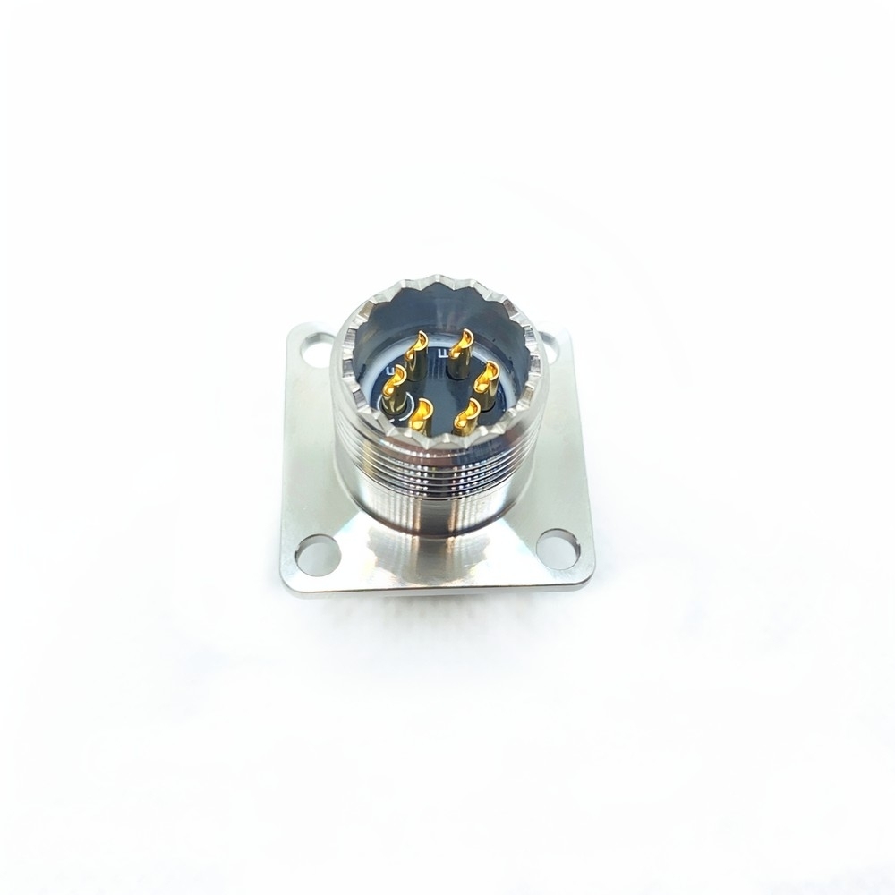
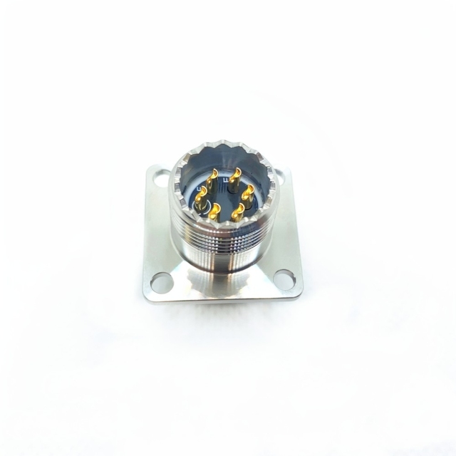
The MS3470S10-06P connector is the narrow flange receptacle of the MIL-DTL-26482 Series II family: a panel-mount military circular connector with a square flange, a circular coupling body and a pin contact interface. It is the half that stays fixed to the equipment, and the cable half plugs into it.
Mounting runs through the square flange. Fasteners hold the receptacle flat against a bulkhead, enclosure wall or equipment tray, with the contact face pointing outward and the termination side open inside the box. Shell size 10 keeps the footprint tight, which counts on a crowded panel face where several connectors share the same surface and the drop leads have to clear one another.
Contacts sit on the 06 layout behind a gold-plated pin interface. Because the pins are on the receptacle, the mating plug carries sockets — a bent contact in the field is usually a plug-side repair rather than a teardown of the panel.
Coupling is bayonet: the plug is pushed on, given a short twist and locks, and the keyed shell only lets it seat one way. That is quicker than a threaded couple in a cramped bay, and harder to leave half-engaged.
This is the waterproof military circular connector for the places where a connection has to hold through vibration, salt, weather and temperature swings and still come apart for service — sealed at the interface, plated against corrosion, and built as a form-fit-function equivalent to the qualified part so an existing panel does not need a new cutout.
MIL-DTL-26482 Series II Standard
What the standard governs. MIL-DTL-26482 is the specification for bayonet-coupled circular connectors built for harsh environments. It fixes shell sizes, contact layouts, contact types, keying and the environmental performance a part has to meet, so a Series II receptacle from one production line will mate with a MIL-DTL-26482 Series II plug from another.
Where Series II sits. Series II keeps the bayonet coupling of the family but uses its own shell and accessory system. That is why shell type, shell size, layout and contact code have to be quoted together: a Series I part and a Series II part are not interchangeable even when the shell size looks the same.
What conformance covers. Dimensions, coupling, contact retention and environmental sealing are built to the same document. That is what makes a part-number comparison between one military circular connector supplier and the next meaningful instead of a comparison of appearance.
What it does not cover. Conformance on its own does not mean a programme's formal source approval has been granted, or that a customer-specific drawing revision has been satisfied. Those are the buyer's own qualification steps, and we do not blur the line between them.
Environmental intent. The series is written around vibration, shock, moisture and temperature extremes, and sealing is verified against recognised defence environmental test methods of the kind described in MIL-STD-810.
Drawing discipline. Every MIL-DTL-26482 connector manufacturer works from the same layout tables. Two parts that look identical on the bench can differ in contact size or keying, so the drawing settles what the eye cannot.
Materials & Sealing Construction
Shell and plating. The body is produced in corrosion-resistant materials — aluminium alloy, or nickel-cadmium plated steel where the drawing calls for it. The metal does two jobs at once: it carries the mechanical load of the coupling and it provides the shielding around the contact chamber. Contacts. Precision-machined contacts are plated gold over nickel. The gold layer holds contact resistance low and stable across mating cycles, and the nickel underplate keeps the gold from diffusing into the base metal over years in service. Sealing. O-rings at the interface and a grommet at the rear are what make this a waterproof military circular connector. Finish choice. The same shell type, shell size and layout can be supplied in black anodized, electroless nickel, olive drab cadmium, olive green cadmium or stainless steel passivated finish. If your process specification names a finish, quote the full code on the enquiry rather than describing the colour. Why the maker matters here. Shell material and plating are where a MIL-DTL-26482 connector manufacturer either earns a service life or loses it: plating applied too thin, or a cadmium layer laid down without the right pretreatment, shows up as corrosion long before the contacts fail. We hold plating and sealing to the drawing rather than to a visual standard. Incoming check. Inspect the plating for bare spots, confirm the contacts are seated and locked in the insulator, and check that the O-rings and grommet are in place before the part goes to the panel.
- Bayonet coupling that locks: the plug seats with a short twist and stays seated until it is deliberately released. Keying allows one mating orientation only, so a technician cannot cross-mate two adjacent connectors by feel alone.
- Sealed contact chamber: O-rings at the mating interface and a grommet at the rear close the shell against moisture, dust and splashed fluid. That sealing is what turns a metal shell into a waterproof military circular connector rather than a fair-weather one.
- Vibration and shock resistance: the locked coupling, the keyed shell and the retained contacts work together, which is why this vibration resistant circular connector keeps its contact resistance steady on engine-adjacent panels and vehicle-mounted racks.
- Salt spray resistance: plated shells and gold contact faces resist the chloride attack that eats plain hardware on deck, on the apron and at a coastal site.
- High temperature tolerance: the insulator and the plating are chosen for the wide temperature swings of an avionics bay, an engine accessory zone and an unheated equipment compartment.
- Gold-plated contacts: gold over a nickel barrier keeps contact resistance low and stable through repeated mating, and limits the film build-up that shows up later as an intermittent signal.
- Backshell options: straight and elbow backshells route the cable out in the direction the wiring needs and put the strain relief on the shell instead of on the contacts.
- Shell shielding: the metal body and a grounded backshell contain the interface against EMI/RFI, which helps on panels where switching noise and dense wiring sit close together.
Equivalent Part & Replacement Fit
- What form, fit and function cover: shell type and flange footprint, shell size, contact layout, contact type and gender, keying and orientation, and the mating interface. On those points the part drops into the existing panel and couples with the plug already in service.
- What they do not cover: your programme's source approval, a customer-specific drawing revision, or a qualification report written against another maker's part. Those stay with your engineering and quality team.
- Panel cutout and fasteners: the narrow flange footprint follows the 3470 pattern, so the existing cutout and fastener positions carry over. Check your own panel drawing before the first article goes in.
- Contact gender has to match the plug: the MS3470S10-06P connector carries pins on the 06 layout, so the mating plug must carry sockets. A plug specified with pins will not mate with it, however close the shell size looks.
- Finish and orientation codes: if your process specification calls out a plating or a keying orientation, quote the full code. A part that is otherwise correct but finished to a different code can fail incoming inspection on paperwork alone.
- The price-versus-risk question: equivalence is a dimensional and material claim, not a paperwork claim, and MS3470 connector wholesale pricing does not change that. Ask us for the drawing set for the configuration you need and compare it against the qualified part before a critical line is switched over.
Critical Applications
- Aircraft and avionics: flight control, engine control, navigation and communication boxes, on both fixed-wing and rotary platforms, where the MS3470S10-06P connector has to stay sealed while the airframe cycles hot and cold.
- Ground combat vehicles: tanks, armoured personnel carriers and mobile communication systems, where the panel-mounted half absorbs track vibration and Shock without losing contact.
- Naval vessels: shipboard communication, radar and weapons-control racks, where salt air and washdown are the daily condition rather than the exception.
- Unmanned systems: UAV and UUV data links and power runs, where a connector you cannot easily reach must be right the first time.
- Test and ground support equipment: rack-mounted GSE and test benches that are mated and unmated far more often than a platform connector ever is.
- Satellite and space systems: where weight, reliability and resistance to vacuum and radiation matter — subject to the space-grade qualification your programme requires.
- Rugged industrial equipment: outdoor instrumentation, oil and gas skids, mining and heavy machinery control cabinets that need the sealing and vibration behaviour without a military programme around them.
Part Number & Configuration
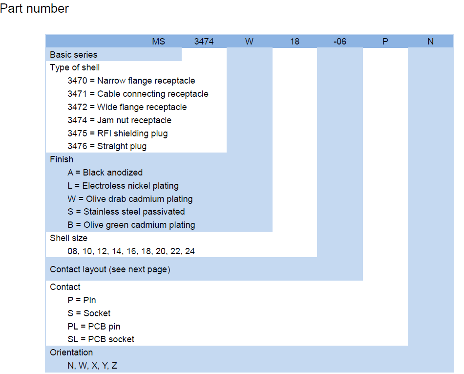
| Position in the string | What it controls |
| Basic series | MS, the military standard prefix |
| 3470 | Narrow flange receptacle — the shell type used here |
| 3471 | Cable connecting receptacle |
| 3472 | Wide flange receptacle |
| 3474 | Jam nut receptacle |
| 3475 | RFI shielding plug |
| 3476 | Straight plug |
| Finish code | A black anodized, L electroless nickel, W olive drab cadmium, S stainless steel passivated, B olive green cadmium |
| Shell size | 08, 10, 12, 14, 16, 18, 20, 22, 24 |
| Contact layout | The two-digit layout code that follows the shell size |
| Contact type | P pin, S socket, PL PCB pin, SL PCB socket |
| Orientation | N, W, X, Y, Z |
| This part | Shell size 10, layout 06, pin contacts |
Mounting & Mating
- Check the panel first. Confirm the cutout, the flange fastener positions and the clearance behind the panel against your drawing before the receptacle goes anywhere near the equipment.
- Seat the flange. Fit the receptacle square to the panel face with the O-ring or gasket in place, and tighten the fasteners evenly so the flange does not distort and load one side of the seal.
- Terminate and load the contacts. Work to your build drawing for the contact type, load each contact into the insulator until it locks, and check retention with a light pull before the shell is closed up.
- Align on the key. Bring the MIL-DTL-26482 Series II plug up to the receptacle on the key and keyway rather than on force — the shell only seats one way.
- Couple and lock. Push the plug home and twist the bayonet coupling until it stops and locks. A coupling that turns freely and never stops is not engaged.
- Verify before sign-off. Confirm the coupling is locked, run continuity and insulation checks across the mated pair, and check that the backshell and grommet have not been disturbed.
- Avoid the usual three faults: a grommet pushed back while loading contacts, an O-ring pinched by an unevenly tightened flange, and a bayonet couple left a few degrees short of the lock.
Ordering & Delivery
- Send the full part number and the quantity. Include the whole string — shell type, finish, shell size, layout, contact type and orientation — because a single character changes the part. We supply the MS3470 connector wholesale from our own production line, so tell us whether this is a one-off replacement or a repeating requirement.
- Confirm the configuration. If your drawing specifies a finish code, a contact type or an orientation that differs from the standard build, say so on the enquiry so the quotation matches the drawing.
- Check availability and lead time. The catalogue shown here is not the full range: a large number of layouts and variants are available but not listed, so ask us to check the exact configuration rather than assuming it is or is not on the shelf. Current lead time is confirmed with your quotation.
- Agree the commercial terms. Payment method and Incoterms are agreed at quotation and confirmed in writing before production starts.
- Plan the delivery. We support Flexible MOQs and Stable global delivery, so a small first order and a follow-on production quantity can run on the same account.
- Ask about samples and packing. If your quality team needs a first article before release, ask your sales contact about sample availability. If your stores need individual bagging, kit marking or a specific carton format, raise it when the order is placed.
Technical Support & Model Matching
Selecting the right connector is rarely a one-line decision. Send us your drawing, part number or a sample, and our engineering team will confirm the matching shell size, contact arrangement, coupling and mounting style, cross-reference discontinued or alternate part numbers, and advise on sealing and flange options for your environment. We also help troubleshoot fit, mating and signal problems, and give installation and commissioning guidance so your line stays up. As a direct manufacturer, our answers come from the people who build the parts — from first enquiry through after-sales support.
- Built to the document, not to a look-alike: dimensions, coupling, contact retention and sealing follow MIL-DTL-26482 Series II, so the part can be compared line by line against the item it replaces.
- Testing before release: lots go through environmental sealing and high-vibration checks, which is the difference between a connector that passes on the bench and one that survives a season in the field.
- Lot-to-lot consistency: plating, contact seating and insulator fit are held to the same settings run after run, so incoming inspection stays a check rather than a gamble.
- Reduced lifecycle cost: a receptacle that does not corrode, loosen or leak takes scheduled replacement and unscheduled downtime out of the maintenance plan.
- Direct from the production line: ordering from the people who machine the shell keeps the specification conversation technical. As a military circular connector supplier we build the receptacle and its mating half to the same drawings.
- A repair path that holds: the locked bayonet couple and retained contacts are what a maintenance team is buying when it specifies a vibration resistant circular connector for a platform it has to keep serviceable.
FAQ
What does the 06 in MS3470S10-06P actually refer to?
The two digits after the shell size are the contact layout code — the code that defines which contacts sit in the insulator and where. Read the whole string as shell type 3470 (narrow flange receptacle), finish, shell size 10, layout 06 and contact type P for pin. Because a layout code alone does not spell out contact count or contact size, ask us for the layout drawing for the 06 arrangement when you need it for a wiring drawing.
Is this part genuinely built to MIL-DTL-26482 Series II?
Yes. It is designed and manufactured in strict compliance with MIL-DTL-26482 Series II and shares the series' bayonet coupling, shell sizes, contact layouts and environmental intent. As a MIL-DTL-26482 connector manufacturer we build to the document rather than to a visual match, so interface dimensions, keying and contact retention can all be checked against the qualified item. Formal source approval for your own programme remains with your quality team.
Will it stay sealed in wet or salt-laden service?
The contact chamber is closed by O-rings at the mating interface and a grommet at the rear, and the shell is plated against corrosion — that is what makes this a waterproof military circular connector on deck, on an apron or at a coastal site. Sealing depends on the couple being fully engaged and on the O-ring being undamaged, so a coupling left short of the lock or a grommet pushed back during contact loading is the usual cause of water ingress.
Can it replace the connector I already have qualified?
The dimensional side is usually straightforward: shell type, flange footprint, shell size, layout, contact type and keying are what make a form-fit-function replacement work, so those are the supports compare first. What we cannot do for you is your programme's source approval or a customer-specific drawing revision. As a military circular connector supplier we will send the drawing set for the configuration you need, so your engineering team can compare it with the qualified part before the switch.
Which mating half does this receptacle need?
A corresponding MIL-DTL-26482 Series II plug of the same shell size and insert arrangement, carrying the opposite contact gender — sockets to mate with the pins on this receptacle. A Series I plug will not couple to it even where the shell size looks the same, because Series I and Series II use different shell and accessory systems.
How do I keep the coupling from working loose under vibration?
Seat it fully. A bayonet couple a few degrees short of the lock feels tight in the hand and will still creep under sustained vibration. Push the plug home, twist until the coupling stops, and check the lock before the equipment goes back into service. Routine inspection should also catch a damaged keyway or a worn coupling, both of which let a vibration resistant circular connector move when it should not.