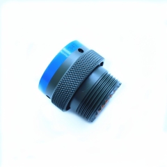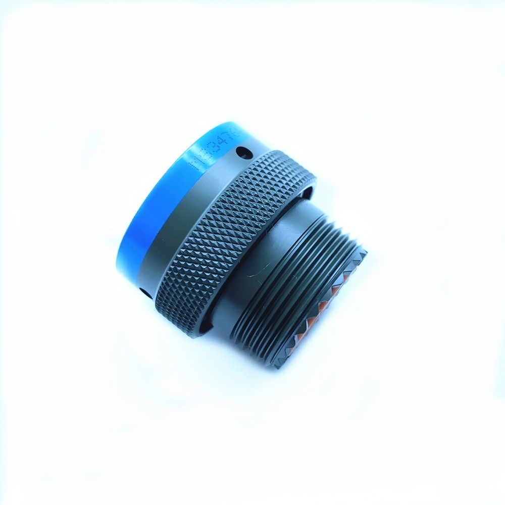
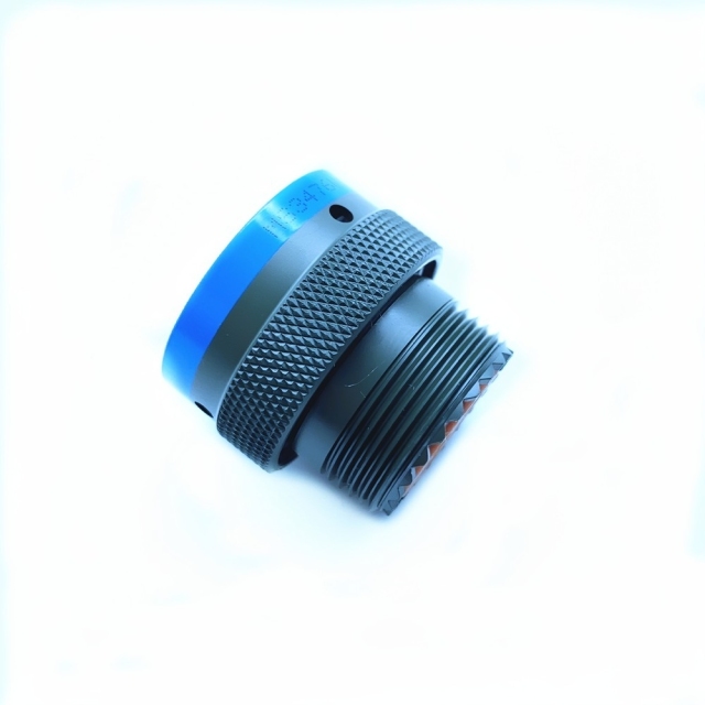
This is the salt-spray member of the MIL-DTL-26482 Series II family — a bayonet-coupled MIL-DTL-26482 connector for equipment that works with salt in the air rather than occasionally near it. The shell is a black-plated metal body with a knurled coupling ring and a blue identification band, so a technician can pick the right circuit out of a crowded panel without tracing the wiring. Contacts sit in a sealed insert and the coupling ring pulls the plug onto its receptacle with a short push-and-twist, so mating needs no tools.
Series II is the bayonet branch of the 26482 specification, written for hardware that has to keep a signal alive through shock, vibration, moisture and temperature swing. In practice that makes this military circular connector a fit for weather-deck junction boxes, dockside control panels, offshore platform instrumentation, and coastal radar and communications cabinets — installations where the salt load is constant instead of seasonal.
It serves new builds and spares equally well. Where a wiring drawing or an equipment nameplate already names a Series II part, this model is the reference maintenance teams match against, and because the interface follows the published dimensions, the mating half does not have to come from the same production run. Like most military electrical connectors built to this series, it is ordered by reference rather than by description, so check shell size and contact arrangement against your own drawing before you commit to a line item.
Salt spray is a slow, patient attack. It works on the plated shell, in the crevice under the coupling ring, on any exposed contact metal, and on the fasteners the connector shares with the enclosure. A part that looks perfect in a dry workshop can show pitting on its coupling surfaces within a season on a weather deck, and that is the point where a bayonet lock starts to feel stiff and a signal starts to wander.
The positions that load a connector this way are easy to list: weather decks, machinery spaces where the air is damp and oily, dockside and shore-power installations, and coastal sites where the prevailing wind carries salt a long way inland. A shell from the general run of industrial circular connectors will often pass its factory test and still fail in that service, because the failure is driven by the atmosphere rather than by the electrical load.
The marine build answers that at the surface rather than in the datasheet. The shell is corrosion-resistant aluminum alloy or nickel-cadmium plated steel, the interface closes against water instead of merely covering it, and the shielding is carried by the metal shell itself rather than by a coating that salt can lift. On this military circular connector the blue identification band does quiet work as well: a fitter can confirm the circuit from the outside, so the connector is opened less often and the seals are disturbed less often.
One field note. Corrosion resistance is a property of an intact assembly, not of a material list. A scratched shell, a seal seated crooked after a rushed re-mate, or a gland left loose will all start the same process. A fresh-water rinse after heavy salt exposure and a look at the coupling surfaces at each service interval will tell you more about the part's condition than any label on the bag.
| Series | MIL-DTL-26482 Series II |
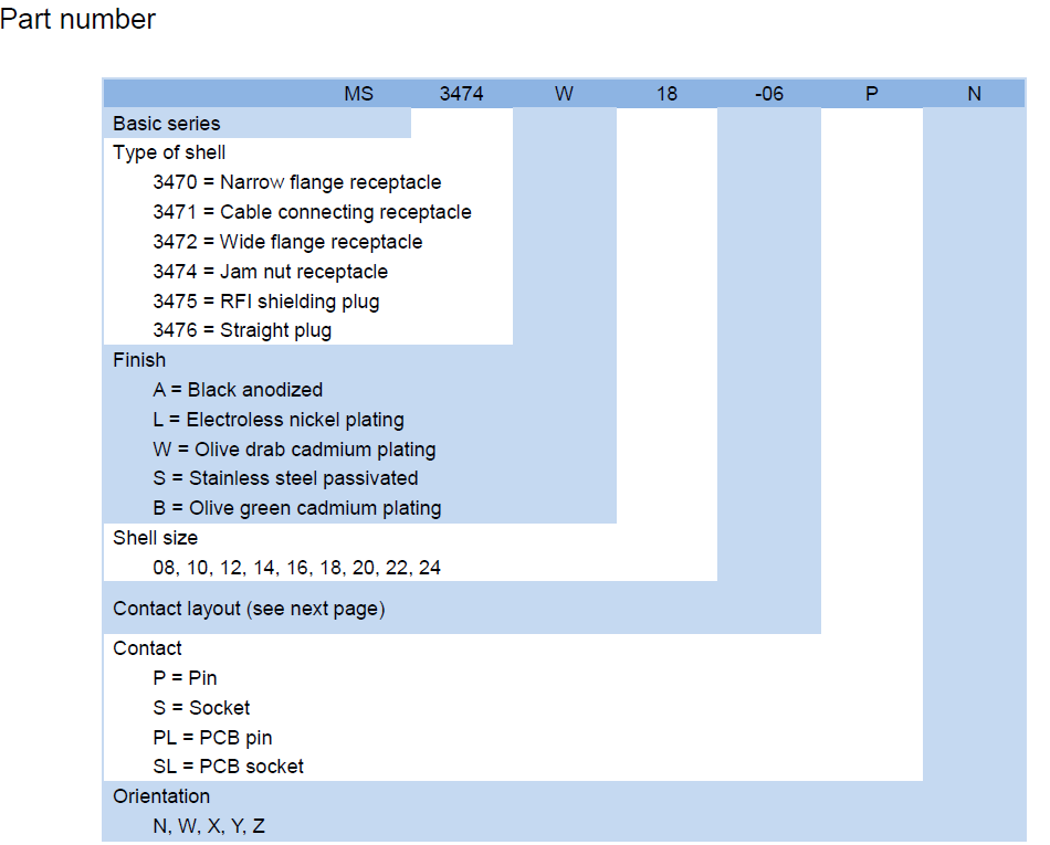
| Model reference | MS3476W14-4PN |
| Coupling | Bayonet, push-and-twist with a positive stop |
| Shell material | Aluminum alloy or nickel-cadmium plated steel |
| Shell finish | Black plated, with blue identification band |
| Contact system | Precision contacts, low contact resistance |
| Contact plating | Gold over nickel |
| Shielding | EMI/RFI protection carried by the metal shell |
| Sealing | O-rings at the interface, rear grommet at the cable entry |
| Service exposure | Moisture, dust, fluids and salt spray |
| Temperature | Wide operating range for aerospace and military service |
| Backshell options | Straight or elbow, for cable routing and strain relief |
Naval work is where this part earns its keep. Shipboard communication racks, radar and weapons-control cabinets, bridge consoles and below-deck power distribution sit in an atmosphere that is permanently damp and often salty, and they are serviced by people who need a MIL-DTL-26482 connector to come apart and go back together in a cramped space. A keyed bayonet lock with a sealed interface answers all three problems at once.
Aircraft and avionics are the second home for the series: flight-control runs, engine-control wiring bundles, navigation and communication suites on both fixed-wing and rotary platforms. Weight and vibration matter more here than salt, which is why the same military circular connector is often specified with an aluminum shell for airborne use and a plated steel shell where it is mounted on structure.
Ground vehicles put the part under a different load — armored personnel carriers, tanks, communications trucks and mobile command posts, where the cable run is stepped on, driven over and washed down. A shell that resists deformation, contacts retained in the insert and a coupling that does not walk loose are what carry it.
Unmanned platforms use the same interface in a smaller envelope: UAV data links, and UUV power and telemetry. Ground support and test equipment uses it because the mating half is already on the bench, which keeps adapter stocks down.
Satellite and space work is a separate question. The part is a candidate where weight, reliability and vacuum behaviour matter, but it is subject to the specific space-grade qualification your program applies — treat that as a qualification item for your engineering team rather than a catalogue claim.
Built to a published specification. The part is made to the MIL-DTL-26482 Series II drawing rather than to a house standard that happens to look similar, so the reference on your bill of materials, the label on the bag and the marking on the shell all describe the same thing. When an auditor or an end customer asks what is installed, the answer is a specification number.
Corrosion is the design brief. Plating, seals and coupling surfaces are chosen for an environment that is wet and salty most of the year. That changes maintenance from reactive to scheduled: a coupling ring is replaced when it is worn, not when a connector has already failed on a weather deck.
The failure that hurts is the intermittent. A dead connector is obvious. A military circular connector that goes high-resistance under vibration, or that backs off a quarter turn in service, is the one that costs a week of fault-finding on a vessel or a platform. Contact retention and a bayonet lock with a positive stop are what keep that from happening.
Lower cost over the life of the equipment. This is a mature, widely specified interface, so parts that follow it are easier to second-source, easier to substitute in an emergency and easier to hold in small numbers than a proprietary connector. The saving shows up in spares holding and downtime rather than on the unit price.
A repeatable source. We buy through MIL-DTL-26482 manufacturer lines that build to the same drawing each time, and every unit is checked for sealing and vibration before it is packed. That consistency is what makes a connector family safe to standardise on across several platforms.
Specifying the right part is easier with an engineer on the other end of the conversation. Our technical team helps you match a requirement to the correct reference — comparing series, contact count, coupling and mounting style against the drawing or part number you already hold — and works through troubleshooting with you when a mated pair or an installed assembly does not behave as expected. We also advise on installation and commissioning practice, and coordinate sourcing, pre-shipment inspection and export documents through our supplier network, so what arrives matches what was agreed.
It mates with the Series II half of the same shell size, keying and contact arrangement — normally a receptacle on a panel or at the end of a cable assembly. The interface dimensions are published, so a mating half from another production run will fit, but the arrangement itself has to match. Send the reference from the receptacle or the cable assembly drawing and we will confirm the pair before you order; among mil spec circular connectors this is the detail worth checking first.
It holds up as long as the assembly stays intact. The plated shell, the sealed interface and the metal-shell shielding do the work, and a scratch through the plating, a grommet seated crooked or a coupling ring left loose restarts the corrosion process. On a weather deck, rinse with fresh water after heavy exposure and inspect the coupling surfaces at each service interval.
Straight when the cable leaves the panel square-on and there is room behind the connector; elbow when the cable has to turn immediately, because it moves the bend away from the contact termination. Whichever you choose, dress the cable so the bend starts behind the strain relief rather than at the contact.
Yes — the interface is the same across the series, and these military electrical connectors appear in avionics as readily as in naval racks. What changes is the shell: aluminum where weight matters, plated steel where the shell takes knocks. Confirm the shell material your platform specification calls for before ordering.
It is a specification part rather than a general-purpose one. If the panel needs a sealed, keyed interface that is documented to a published standard and can be re-ordered by reference years later, this is the right side of that line. If the environment is dry and the duty is light, a general-purpose connector will usually cost less and do the job.
Three things: that keying and contact arrangement match the receptacle, that the interface seal is present and undamaged, and that the coupling ring turns freely through its full travel. A replacement that feels stiff on the first turn usually has a damaged ring or a misaligned keyway.