The Board-Side Half of a Series III Pair
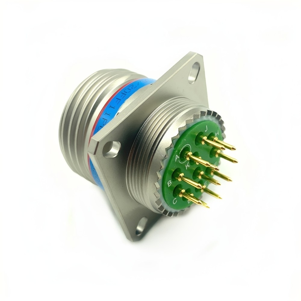
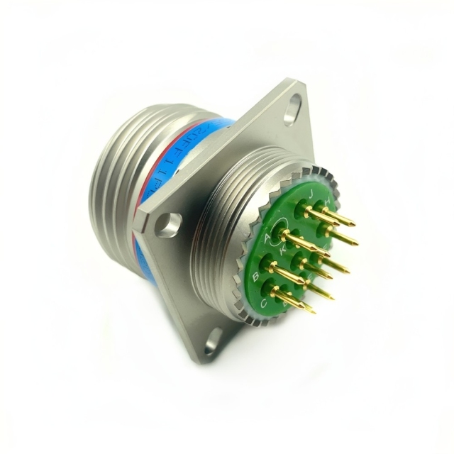
This MIL-DTL-38999 Series III circular connector is the fixed half of a pair: a square flange receptacle whose four screws pull the flange flat against a panel, a bulkhead or an equipment housing while the plug stays with the cable assembly. What sets it apart from a wire-terminated receptacle is the back of the insert — PC short PCB pins stand out of the shell and solder into plated through-holes, so the termination sits inside the enclosure instead of inside a backshell. The contacts are gold-plated copper alloy, rated 5 A for signal circuits and 23 A for power feeds, and where a hybrid layout is needed, signal, power, coaxial and high-speed data contacts can share the same shell. Coupling is the Series III triple-start thread. Three starts pick up together, the plug comes down in a short turn, and it cannot back off unless the thread is turned out deliberately. A program that already specifies an aerospace D38999 connector on the cable assembly usually keeps the same interface here, so the mating plug is already defined.
How the Shell Copes With Salt, Heat and Vibration
- Salt air and wash-down. The electroless nickel layer is the surface that has to be salt spray resistant; it absorbs corrosion and scuffing while the aluminium alloy underneath stays sound, which is why this finish appears on shells that are handled, wiped and cleaned often.
- Water. The interfacial seal closes only when the halves mate, and the flange gasket closes the joint at the panel. Treat the plug, its backshell and this receptacle as one waterproof military circular connector assembly, because an open shell or an open cable entry is not a sealed joint. A high temperature military connector is judged on whether the pins keep their position and the seal recovers, not on whether the shell survives a soak.
- Vibration. With the coupling fully home, thread preload holds the plug against the flange, which is why the shell is specified as a vibration resistant circular connector on engine brackets, suspension pans and airborne racks.
- Shock. A keyed insert and sprung contact sleeves keep the interface stable at the 100 G shock level the series is rated for, so a hard landing or a strike under a vehicle does not walk a pin out of its hole — the trait a shockproof military circular connector is picked for.
- Mass. An aluminium shell on a gimbal, a rack shelf or a rotating mount adds very little weight, which counts on UAV and satellite hardware.
Fitting It to a Board and a Panel
- Check the flange outline and the four fixing holes against the panel drawing before any hole is drilled; a burr under the flange tips the shell and loads one side of the gasket.
- Solder the PCB pins into the board with the shell held square, and let the joints cool before the flange is drawn down, so the pins do not carry panel load.
- Fit the panel gasket, set the flange in place and tighten the screws in a cross pattern; the gasket is the half of the seal that lets the installed receptacle behave as a waterproof military circular connector.
- Keep the insert dry and free of chips while the board is handled; a smear of flux or a stray strand across the contact face is the usual reason for a poor reading at first power-up.
- Line the keyway up and start the triple-start thread by hand. It should pick up without force; if it fights, the halves are not keyed correctly and turning harder will damage the thread.
- Turn the coupling down until it bottoms out, then fit the backshell, boot or strain relief that matches the cable diameter so the plug carries the cable load rather than the contacts.
- On a mount that shakes, add the locking accessory or safety wire your work instruction calls for, and check continuity again once the loom is routed and clamped.
Where This Flange Gets Bolted Down
Avionics racks and instrument panels are the usual home: the unit carries the board, the flange is fixed to the unit wall, and the aircraft loom plugs in from the front. Dash panels, weapon-station controls and power distribution boxes on armoured vehicles use the same arrangement through a bulkhead, and radar or missile-guidance racks, flight data recorders and UAV or satellite subsystems take it where the board is the reference and the cable is the part that moves.
Shipboard and offshore cabinets are harder on any plated shell, and industrial assemblies — oil and gas sensors, maritime navigation, emergency-response equipment — borrow the same sealed, keyed interface where a commercial connector is not worth the risk. What these installations share is a panel that stays put while the plug is worked, cleaned or replaced.
Configuration and Ratings for 20FF11PCN
| Build detail | Specification |
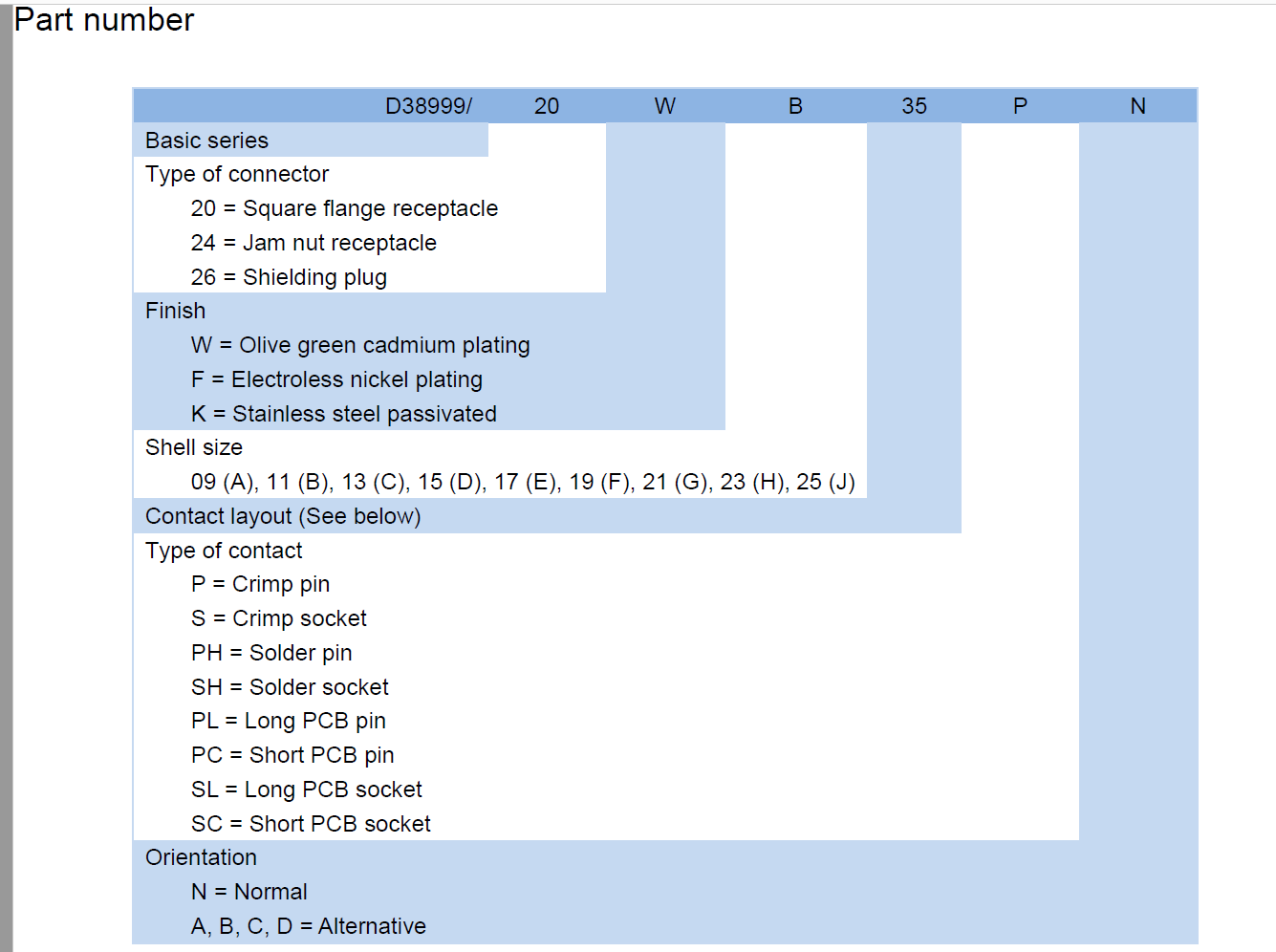
| Part number | D38999/20FF11PCN |
| Shell style | Square flange receptacle, four fixing holes |
| Shell size | 20 |
| Contact layout | F11, 11 contacts |
| Contact style | PC, short PCB pin |
| Contact material | Gold-plated copper alloy |
| Signal current | 5 A per contact |
| Power current | 23 A per contact |
| Voltage rating | 1,500 V AC RMS |
| Shell material | Lightweight aluminium alloy |
| Shell finish | F, electroless nickel |
| Coupling | Triple-start thread |
| Sealing | IP67 / IP68 |
| Operating temperature | -65 °C to +200 °C |
| Vibration and shock | 10–2000 Hz, 100 G |
Details to Settle Before Release
Quote the complete part number with the F finish, the F11 layout and the N keying, because changing any one field produces a different connector. If the drawing predates the current build, send it as it stands and we will cross-reference each field against what we make. Two fields account for most of the back-and-forth: contact style, where PL long PCB pins replace the PC tails when the board sits further back inside the housing, and keying, where A, B, C and D positions exist so two similar connectors on one panel cannot be cross-mated.
Say what should travel with the goods. As a D38999 connector factory we can confirm which documents accompany a batch — traceability paperwork, test records and a packing list — and note any export classification your program needs at the quotation stage. As a MIL-DTL-38999 connector manufacturer we keep finish, layout and keying on file, so a repeat order matches the first and the board drawing does not need touching.
A repair depot order and a production order need different handling, and a military circular connector supplier who knows which is which can keep later deliveries consistent. Tell your sales contact which one applies when the order is placed.
Technical Support & Model Matching
Choosing the right shell size, contact arrangement, keying and coupling for a cable assembly is where most ordering problems start, so our engineers work through it with you before anything is shipped. Send a part number, drawing or photo of the connector you are replacing and we will cross-reference it against our MIL-DTL-38999 range and confirm the closest equivalent. After delivery we stay available for mating and installation guidance, wiring questions and fault finding, and we are glad to quote bulk orders and custom designs.
FAQ
Can the PCB pins be soldered straight into the board?
Yes. The C code means short PCB pins, made to pass through plated holes and be soldered on the board side, so the termination sits inside the enclosure rather than a backshell. Where the shell stands further off the board, the same receptacle is built with PL long PCB pins. Solder the receptacle to the board before the flange screws are drawn down, so the pins are not carrying panel load while the joints cool, and the mating half is a standard aerospace D38999 connector plug carrying socket contacts.
Does the F finish stand up to salt air and wash-down?
Electroless nickel — the F in D38999/20FF11PCN — is a hard, cadmium-free layer over the aluminium alloy shell, and it is the surface that has to be salt spray resistant on a coastal or deck installation. It resists abrasion from handling and cleaning, and it keeps a conductive path to the panel at the flange. Where a drawing permits cadmium, the same series is offered with the W olive green finish, so match whichever finish your specification names rather than substituting one for the other.
How much current can the 11 contacts carry?
Each contact is rated up to 5 A for signal circuits and up to 23 A for power feeds, with the connector rated 1,500 V AC RMS. The F11 layout uses 11 contacts, and because mixed contact types can share one shell, signal, power, coaxial or high-speed data lines can run through the same housing. The current figure is per contact, so plan the split across the 11 positions with the layout chart in front of you.
Does the insert hold its contacts at the top of the temperature range?
The connector is rated from -65 °C to +200 °C, and at the top of that band the insert and the contact retention clips decide behaviour rather than the shell. Whether a location needs a high temperature military connector or a standard build comes down to the working temperature and the dwell time at the panel, so send both figures with the drawing. As a MIL-DTL-38999 connector manufacturer we can confirm what a given build is rated to before it is released.
What keeps the coupling tight on a panel that vibrates?
The triple-start thread holds it. Once the coupling is turned fully home, the halves cannot separate without the thread being driven back, which is a different failure mode from a latch that can pop under shock — the reason this shell is specified as a vibration resistant circular connector on engine brackets and airborne racks. Seat it fully at assembly and check it at each scheduled inspection, because a coupling left part-way will work loose long before a fully seated one. As a D38999 connector factory we can confirm which locking accessory suits the shell.