Product Overview
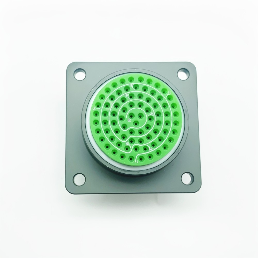
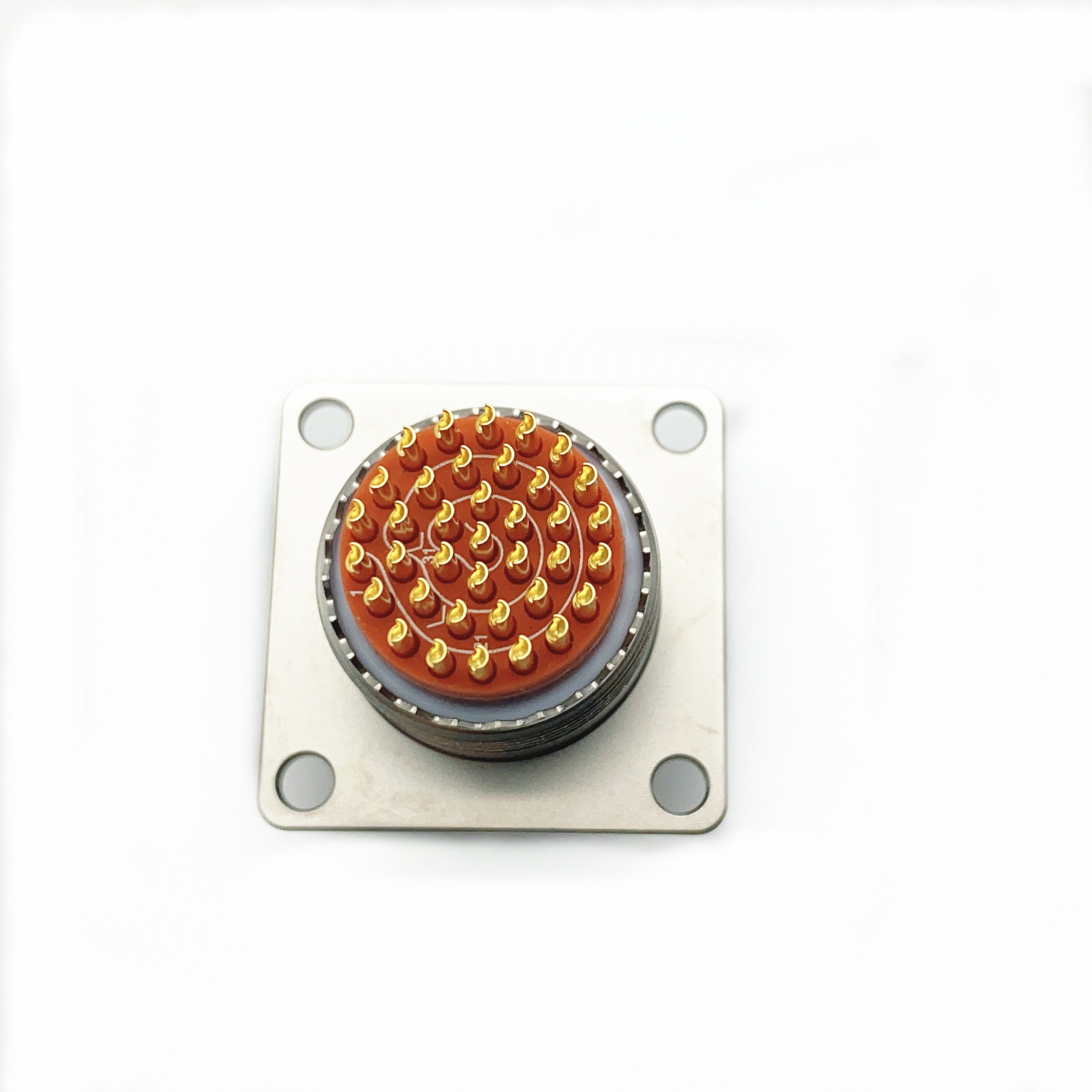
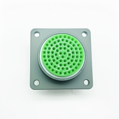
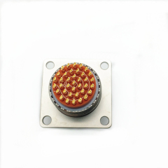
The MS27496E21B35PN is a box mounting square receptacle from the MIL-DTL-38999 Series I range, built in shell size 21 with pin contacts and an olive green cadmium finish. The body bolts through a panel on four corner holes, the keyed circular interface stands proud of the flange so a plug can couple from outside the enclosure, and the contacts terminate behind the panel.
That shape makes it the panel-side half of a connection rather than a cable-end part. Equipment builders use it where a cable bundle has to enter a sealed box and still be unplugged for service — avionics racks, ground vehicle hulls, shipboard cabinets, outdoor control enclosures. Maintenance teams fit the same receptacle as a replacement when the original has worn contacts or a damaged flange.
The design keeps two jobs in one package: carrying the mechanical load of the coupling through the shell, and holding every contact in a fixed position inside the insert. Sealing sits between the interfaces rather than depending on the cable bundle, so the assembly stays connected through vibration, salt-laden air, heat cycling and washdown instead of needing periodic re-termination.
Every MIL-DTL-38999 Series I connector in this range shares the same shell and contact code, so a program that already specifies the series can add this receptacle without relearning the numbering — an existing plug will mate it once shell size, layout and key position match.
As a MIL-DTL-38999 connector manufacturer we build the receptacles, the matching plugs and the rear accessories together, so the mating interface stays consistent whether you order one piece for a repair or a production quantity for a new build.
Avionics and flight equipment. Flight control, navigation and communication units use this class of receptacle where a cable assembly leaves the rack and has to be disconnected for line maintenance. Ground support equipment and test benches pick the same part because the keying and coupling are built for routine service access. Military ground vehicles. ECU interconnects, sensor networks and cable junctions inside a hull see continuous vibration, temperature swing and washdown, and a sealed receptacle keeps those circuits continuous without a separate environmental boot. Where a cable assembly has to leave a sealed enclosure, this aerospace plug socket connector gives the panel a defined, keyed interface instead of a cable gland — a repeatable mate and a part number that can go on a drawing. Industrial robotics and moving machinery. Articulated arms, indexing tables and gantry axes put connectors through constant acceleration, and a vibration resistant circular connector keeps the signal stable where a general-purpose part would fret at the contacts. Satellite payload interfaces, undersea monitoring housings and medical imaging equipment such as MRI and CT interconnects round out the list. These are low-volume, high-consequence builds where the connector is chosen for what it does when something goes wrong rather than for unit price. Shipboard and outdoor control cabinets. Salt air, driven rain and continuous operational stress are the normal conditions, so the cadmium-plated shell and sealed interfaces are what let the cabinet stay closed and the electronics stay dry.
Materials, Plating & Contacts
- Aluminium shell, cadmium finish — the shell is machined from aluminium alloy and cadmium plated for corrosion resistance, with olive green cadmium as the standard finish on this part.
- Gold over nickel contacts — beryllium copper C17200 contacts carry 50 microinches of gold over 100 microinches of nickel underplate; the nickel barrier stops base-metal diffusion and the gold keeps contact resistance stable through repeated mating.
- PTFE-based dielectric — the insert is a PTFE-based composite chosen for low dielectric loss, which matters on signal-heavy layouts where capacitance between neighbouring contacts would otherwise blur the signal.
- Hybrid contact geometry — power and signal contacts share the insert with an optimised geometry that keeps cross-talk down when high-current and low-level lines run side by side.
- Termination options — the P code on this part is a crimp pin; solder-cup contacts give a robust, gas-tight soldered joint where a drawing calls for them, and PCB tail versions suit board-mounted interfaces.
- Backshell compatibility — the interface accepts M85049 EMI filter backshells without compromising performance, and shielding is characterised from the MHz band up to 10 GHz.
- Consistent across the range — every MIL-DTL-38999 Series I connector here uses the same insert and contact materials, so a replacement behaves like the part it replaces instead of introducing a new contact alloy into a qualified assembly.
- Built in our own plant — we machine and assemble the connector in our own factory rather than reselling finished units, which is what lets an aerospace connector manufacturer hold contact geometry and plating thickness to one specification across lots.
Vibration & Mechanical Stability
The receptacle holds contact through movement because the load path runs through the shell and the flange, not through the contacts. The plug couples onto the keyed interface, the insert locks each contact into its cavity, and the four-hole flange clamps the body to the panel, so cable-bundle pull and panel flex stay out of the contact zone.
Vibration performance is verified to MIL-STD-202 Method 204. That is the sweep used to check whether contacts stay mated and electrically quiet while the assembly is shaken across the frequency band, and a part that passes it can be mounted on an engine-adjacent structure, a vehicle hull or a moving machine frame with continuity expected rather than intermittent faults. That is the practical meaning of a vibration resistant circular connector.
Shock resistance comes from the same structure. Impact loads are taken by the shell and the panel flange before they reach the insert, which is what matters on land vehicles, deck equipment and anything handled roughly during deployment.
Mating durability is rated at 500 cycles minimum without degradation of the electrical parameters. For a test bench or an access panel opened at every inspection, that figure is the difference between a connector that survives the maintenance schedule and one that becomes a recurring line item.
Two mechanical details decide how well it holds in service. Mount the receptacle flat against the panel, because a distorted flange lets the body flex under coupling loads. And support the cable bundle behind the panel so cable weight is carried by a clamp rather than by the backshell. Airframe and vehicle programs generally specify the test method rather than accept a claim, and an aerospace connector manufacturer who can quote MIL-STD-202 Method 204 by name is giving you something you can put in a qualification file.
Sealing & Environmental Protection
- Three sealed interfaces — the connector interface, the mating interface and the cable entry are closed with conductive elastomer gaskets, so moisture has to cross a deliberate barrier rather than a joint line.
- Rated when mated — the assembly meets IP68 requirements when mated with a proper backshell. The rating belongs to the mated pair, not to a bare receptacle on a bench, and that is what makes it a waterproof military circular connector rather than a splash-resistant one.
- Hermetic option — the sealing is tested to 15 psi differential for panel feedthroughs and pressurised compartments where a leak path through the connector is unacceptable.
- Salt spray resistance — the cadmium-plated shell and sealed interfaces are intended for marine decks, coastal installations and road-salt exposure, where unprotected aluminium would pit within a season.
- Heat and thermal cycling — the insert, contacts and sealing materials are selected for continuous operation across the rated span and for the cycling that comes with it; a high temperature circular connector has to hold its sealing force while the shell expands and contracts.
- Flame resistance — the materials carry a V0 flame-resistance rating, which counts inside equipment bays where a fault could put the connector near an ignition source.
- What breaks the seal — a damaged gasket, an unmated receptacle left open in the field, or a backshell that does not suit the shell. Cap unmated receptacles and replace gaskets after a service break rather than reusing them.
Mating Check & Traceability
- Inspect before mating. Look at the insert and the pins for bent contacts and check the keyway for damage or debris — a contaminated keyway is the usual reason a plug will not seat.
- Align the key position. A normal receptacle accepts only a normal plug, and an A, B, C or D orientation accepts only its matching alternative; the keying exists to prevent cross-mating.
- Seat the plug by hand until the coupling engages, then complete the coupling. Never force past the point where the keyways meet — resistance there means the wrong orientation, not a tight fit.
- Confirm the mate visually. The colour-coded keying system gives a no-tool check of full engagement, so a technician can verify the joint without a gauge or a torque wrench.
- Record the serial. Each unit carries a laser-etched serial number on the shell; log it against the equipment rather than against the box it arrived in, because the box is what gets thrown away.
- Keep the record with the unit history. The serial ties the part to its build lot, finish and contact type, which makes a fault traceable to a batch instead of a guess.
- Reordering then becomes a lookup rather than an investigation — quote the serial or the code, and as a military circular connector supplier we can match the same build again years later.
Part Number & Shell Options
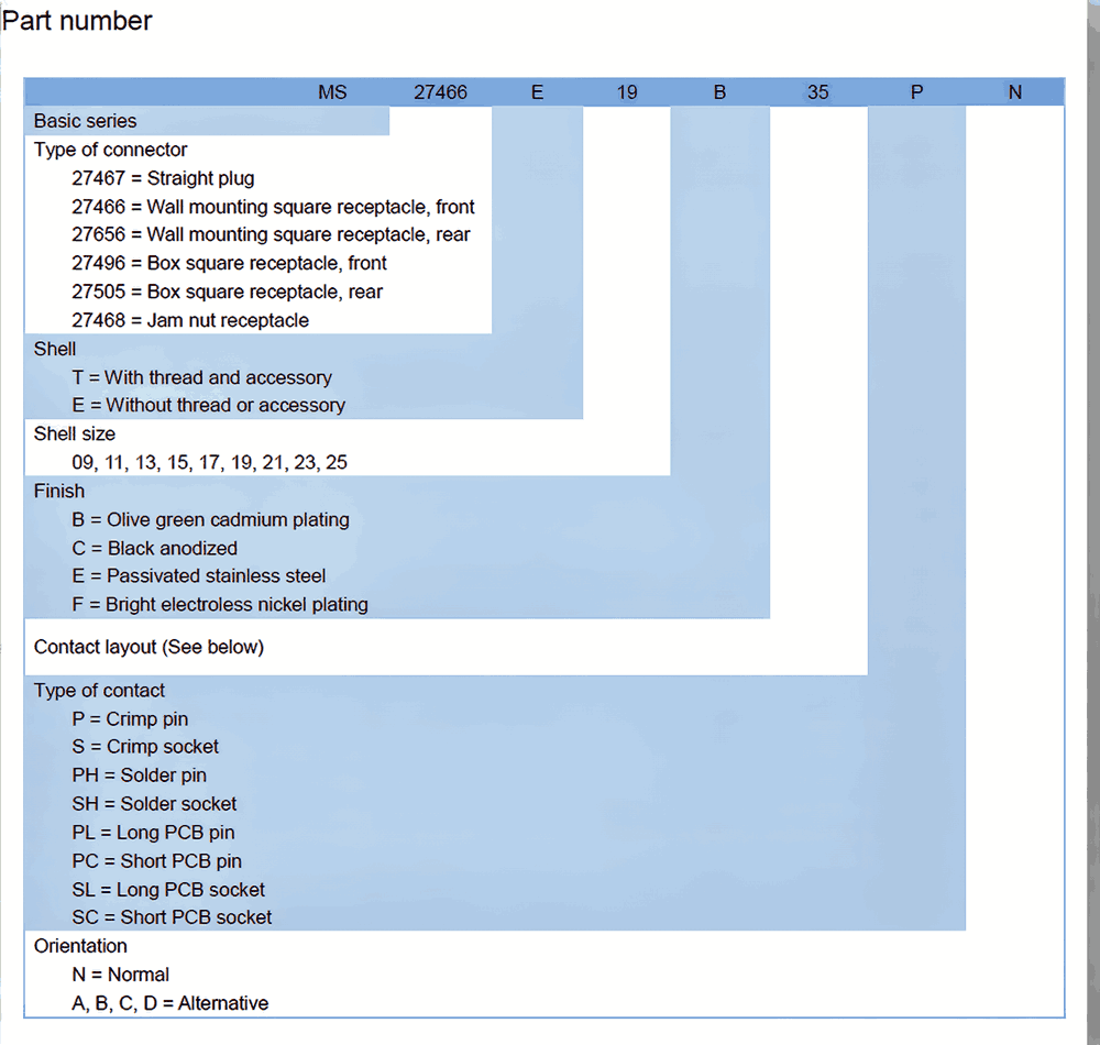
- Start with the connector type block. The first characters read 27496 — the box mounting square receptacle with front mounting. The same series also covers 27466 and 27656 wall mounting square receptacles, front and rear, 27467 straight plugs, 27468 jam nut receptacles and the 27505 box square receptacle in its rear-mounting form. Whichever block you pick, the rest of the string describes one specific aerospace plug socket connector.
- Read the accessory letter next. T means the shell is supplied with a rear thread and accessory; E, as on this part, means without thread or accessory, so the backshell is specified separately.
- Take the shell size — two digits from 09 through 25. This one is 21, which sets the flange footprint, the panel cut-out and how many contacts the layout can carry.
- Finish follows. B is olive green cadmium plating, C is black anodized, E is passivated stainless steel and F is bright electroless nickel. Most programs keep the same finish on both halves of a mated pair.
- Then the contact layout, two digits such as 35, which fixes the contact count and the arrangement inside the insert.
- The contact type letter tells you what you are terminating: P crimp pin, S crimp socket, PH solder pin, SH solder socket, and PL, PC, SL and SC for long and short PCB pins and sockets. If your application sees high oil exposure, a C1 suffix at the end of the part number specifies fluorosilicone sealing; a C2 suffix adds a conductive square flange gasket.
- The final letter is the key position. N is normal, and A, B, C and D are alternative orientations that stop two adjacent connectors being cross-mated.
- If a drawing quotes only part of the string, send what you have. As a military circular connector supplier we confirm the full code — finish, contact type and key position — before the order goes into production.
Key Specifications
| Specification | Value |
|---|
| Standard | MIL-DTL-38999 Series I |
| Connector type | Box mounting square receptacle, front mounting |
| Shell size | 21 |
| Contact layout | 35 |
| Contact type | Pin contacts (P) |
| Keying | Normal (N) |
| Shell finish | Olive green cadmium plating (B) |
| Operating temperature | −65 °C to +200 °C |
| Current rating | 5 A per contact, derated across the temperature range |
| Voltage rating | Altitude dependent |
| Contact plating | Gold over nickel underplate |
| Vibration | MIL-STD-202 Method 204 |
Ordering & Delivery
| Term | Detail |
| Minimum order quantity | Flexible MOQs |
| Delivery | Stable global delivery |
| Non-standard configurations | Quoted against the full code on your drawing |
| Rear accessories | Backshells and strain relief quoted with the connector |
| Lead time | Confirmed at quotation against quantity and configuration |
| Packing | Agreed with your quotation for the destination |
| Test and material records | Discussed at enquiry against your quality plan |
Technical Support & Model Matching
Selecting the right connector is rarely a one-line decision. Send us your drawing, part number or a sample, and our engineering team will confirm the matching shell size, contact arrangement, coupling and mounting style, cross-reference discontinued or alternate part numbers, and advise on sealing and flange options for your environment. We also help troubleshoot fit, mating and signal problems, and give installation and commissioning guidance so your line stays up. As a direct manufacturer, our answers come from the people who build the parts — from first enquiry through after-sales support.
- 1. 100% electrical continuity testing on every unit — a full test, not a sample from the batch.
- Automated optical inspection of contact alignment, which catches a contact seated off-centre before it ever reaches a connector assembly.
- Salt spray testing to ASTM B117 for 500 hours, the check behind the corrosion resistance rather than a visual look at the plating.
- Ten thermal shock cycles across the full rated temperature span; that cycling is what the high temperature circular connector rating rests on.
- Insert retention force verification at 70 N minimum, the measurement that predicts whether a contact can be pushed back out during mating.
- Every MIL-DTL-38999 connector manufacturer works to a test plan, and ours is written around the environmental and mechanical conditions this part is actually sold for.
- If your quality plan needs specific evidence — continuity records, plating thickness, salt spray results — tell us at enquiry and we will confirm what can be supplied with the lot.
FAQ
What applications is this connector suited for?
It is the panel-side half of a connection on aircraft and avionics assemblies, military ground vehicles, shipboard and outdoor control cabinets, satellite payload interfaces, industrial robots and imaging equipment. The receptacle bolts to the enclosure and the plug mates from outside, so it suits any cable run that has to enter a sealed box and still be disconnected for service. Most programs specifying a vibration resistant circular connector are working on a moving or vibrating structure, which is exactly what this part is built for. We supply it as a military circular connector supplier for new builds and for replacement work.
Can I use this connector in harsh environments?
Yes. The design covers vibration, salt spray, high temperature, moisture and shock, and the shell is cadmium plated so corrosion does not begin at the flange. Two conditions matter. First, the IP68 rating applies to the mated pair, not to a bare receptacle. Second, the seal depends on the backshell you fit, so the rating follows the assembly you build. Put together correctly it is a waterproof military circular connector, and it holds its sealing force through thermal cycling. The high temperature circular connector rating covers the full span shown in the specification table.
Is this available as an aerospace plug and socket?
Yes — the receptacle is one half of an aerospace plug socket connector assembly. The plug carries the coupling and the receptacle bolts to the panel, and both halves come from the same series, so a plug ordered to the same shell size, layout and key position will mate it. Send the plug code with your enquiry and we will check the pair before shipment; as an aerospace connector manufacturer we hold both halves of the series rather than only the receptacle.
Do GJB599B-numbered connectors mate with this one?
They do. GJB599B designations use a JY prefix where MIL-DTL-38999M designations use MS, and for the same section the two are interchangeable and mating-compatible, so this MIL-DTL-38999 Series I connector will mate the equivalent GJB599B part. Check that shell size, contact layout and key position match, and quote the prefix your drawing uses so the right designation goes on the paperwork. Where the application calls for high oil resistance, a C1 suffix specifies fluorosilicone sealing; a C2 suffix adds a conductive square flange gasket.
What should I check before ordering a replacement?
Read the marking on the old shell rather than working from the drawing alone. A part that looks identical but ends in S instead of P has socket contacts, and a C finish instead of B is black anodized rather than olive green cadmium — either will fit the panel, and neither will match the wiring already built. Photograph the marking and send it with the enquiry; we will read the code back to you before anything is quoted.