Product Overview
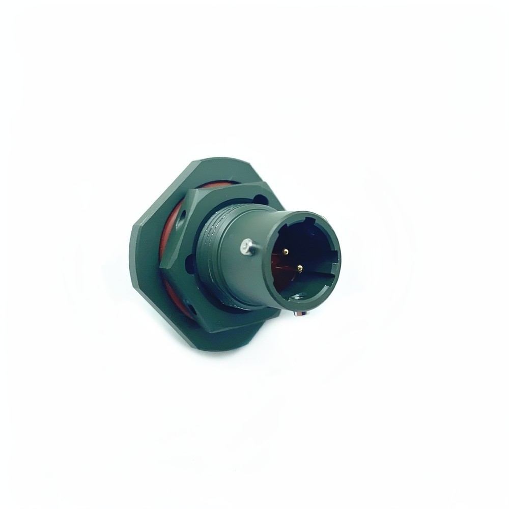
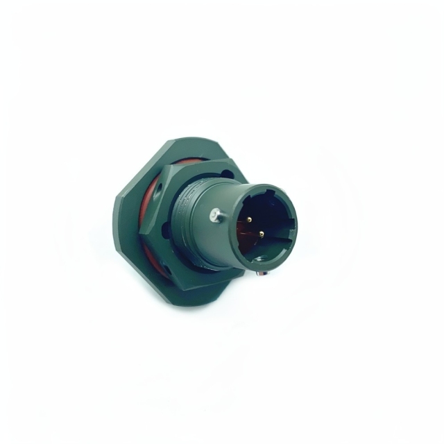
The MS3114E08-02PNB is the jam-nut receptacle half of a MIL-DTL-26482 Series I coupling: the part that is fixed through a panel or bulkhead while the cable plug mates into it from the outside. As a MIL-DTL-26482 crimp connector it takes contacts that are crimped onto the wires and then inserted into the insulator, so a wiring assembly can be built at a bench and serviced later without soldering inside the shell. Because it is the fixed half, most installations use it where the wiring runs inside an enclosure and only the coupling face is exposed — instrument panels, junction boxes, equipment bays and bulkhead pass-throughs. It pairs with a Series I plug of the same shell size and layout, and it is built to stay compatible with wiring assemblies already drawn around legacy Series I hardware. The wider range covers plugs, receptacles and loose contacts, so a build can be sourced from one MIL-DTL-26482 circular connector manufacturer rather than pieced together from several. If you are working from an existing drawing, what you actually need is defined by shell size, layout and contact gender rather than by the housing style alone.
Crimp Termination and Contact Handling
- Match the wire to the contact: check the conductor gauge against the contact size your layout uses before stripping anything, and remember that the rear grommet also has to close on the outside diameter of the wire.
- Strip to the crimp barrel and no further: the conductor should fill the barrel with the insulation entering the rear of the contact, so no bare conductor is left outside the crimp.
- Crimp with the matched tooling: use the crimp tool and positioner specified for the contact, and pull-test the first few crimps before running the full wire bundle.
- Insert until the contact seats: the contact should go into the insulator with its retention clip engaged, and a light tug confirms it is locked rather than merely pushed in.
- Route each wire through its own grommet hole: one wire per hole. Crossing wires or doubling up in a single hole breaks the rear seal and is invisible once the shell is closed.
- Test before the assembly goes onto the panel: continuity, insulation resistance and a visual check on contact depth are far cheaper at the bench than after the receptacle is mounted and the wire bundle is dressed.
- Re-termination is a contact change, not a full cable rebuild: if a lead fails in service the contact can be extracted with the proper tool and the circuit rebuilt. That is the practical reason to specify a MIL-DTL-26482 crimp connector rather than a solder version, and the case a MIL-DTL-26482 circular connector manufacturer makes for crimp contacts over solder joints.
Advanced Environmental Sealing
That rating belongs to the coupled pair, with the mating plug fully engaged. An open receptacle is a protected but not a submersible interface, so cover it during build and transit. The E element in the code is the rear seal: a grommet that closes around each individual wire as it leaves the insert. It is what keeps moisture, dust and splash out of the contact chamber once the cable assembly is built, and it is the part of the IP68 military circular connector rating that the wire itself has to complete — which is why the outside diameter of the wire matters when you select contacts and cable. Temperature is the other half of the environmental story. The chemical-resistant thermoplastic insert is chosen to keep its dimensions and dielectric behaviour across that band instead of softening or embrittling at either end of it. In practice the seal depends on what happens at the panel as much as on what happens inside the shell. A clean, correctly sized cut-out, a seated panel gasket and a properly tightened nut keep the seal path continuous; a burred or oversized hole gives moisture a route around the housing that no grommet can close. Where an installation is washed down, steam-cleaned or regularly immersed, tell us the fluid and the cleaning regime. A sealing class covers water and dust; resistance to particular solvents, fuels or hydraulic fluids is a separate question with a separate answer.
Enhanced Mechanical Durability
Cadmium sacrifices itself before the base metal does, so the housing keeps its integrity on a deck, at a coastal site or on a vehicle that lives outdoors. The olive green tone is the plating itself, not a paint coat that can chip away from the edge of a flange. That figure is what a maintenance planner works with: a coupling that is unmated for test, inspection and cable assembly swaps still has margin in reserve at the point where a lighter connector would already be showing wear on the coupling pins and keyways. Bayonet coupling is part of how that life is reached. A short turn locks the halves instead of drawing them down on threads, so mating is quick and the wear lands on the coupling surfaces rather than inside the contact chamber. The housing also absorbs what the insert should never see. Drops, cable pulls and the weight of a cable assembly hanging off the coupling load the shell first, and a metal body spreads a shock load across the flange instead of concentrating it on a polymer thread. A locking bayonet coupling on a rigid metal shell is also what makes this a vibration resistant circular connector rather than only an IP68 military circular connector: the cable assembly mass is carried by the housing and the coupling does not walk back under continuous movement. Where a program needs a different plating, that is a suffix change rather than a new design — the shell geometry, insert and coupling stay exactly the same.
Compliance and Certification
The connector is built to MIL-DTL-26482 Series I, Revision G requirements — the specification that defines the shell dimensions, the coupling, the insert arrangements and the environmental tests the interface has to survive. Conformance here means the part will mate with other Series I hardware built to the same revision, which is what keeps a legacy cable assembly serviceable.
Manufacturing runs under ISO 9001:2015, and every connector goes through environmental sealing and high-vibration checks before it leaves the line. As a MIL-DTL-26482 circular connector manufacturer we test against the standard rather than against a competitor's sample, so the part on your bench and the part in the field are the same build.
RoHS and REACH compliant versions are available in the range. The standard finish on this part is cadmium plating, which falls outside RoHS scope in some markets. If your supply chain is restricted, a MIL-DTL-26482 connector supplier should be matching the plating code to your restriction list before the order — tell us which code your program requires and we will do exactly that, rather than leave it to be discovered at incoming inspection.
What a compliance statement does not do is qualify the part for your program on its own. Qualification is a program decision that depends on the platform, the cable assembly and your approval route, so it is worth confirming early what your quality team needs to see with the shipment.
Ruggedized Installation Features
- Jam-nut mounting through one hole: the receptacle passes through a single round cut-out and is drawn up by its nut from inside, so the panel needs a flat seating face rather than a four-hole flange pattern.
- Seal the panel face first: fit the panel gasket against a clean, burr-free surface before tightening. As an environmentally sealed circular connector the housing only keeps water out of the enclosure if the joint between shell and panel is closed before anything else.
- Tighten to seat, not to crush: the nut should pull the shell flat against the panel without deforming it. A distorted flange is the most common cause of a leak that then gets blamed on the connector.
- Keyway before coupling: the key and keyway align the halves before the contacts meet, so a plug can only go on one way and only with the matching shell size and layout.
- Couple all the way: a bayonet that is only part-turned will feel engaged and will not hold the seal. Turn until the coupling locks, then check that the two halves cannot be rocked apart.
- Leave a service loop: a short length of slack behind the receptacle keeps the cable weight off the rear seal and gives a technician room to work when a contact has to come out.
Series I Part Number Reference
- Built to the Series I standard: this military circular connector OEM build follows the same shell, coupling and insert geometry as the rest of the family, so plugs, backshells and mounting hardware already qualified for the standard remain usable.
- Interchangeable by number, not by brand: interchangeability is set by shell size, layout, contact gender and key position, which is what makes a second source practical on a running program.
- Key position as a safety feature: the N keyway is standard here, and alternative keyways in the same shell size let two adjacent connectors on one panel be made physically non-interchangeable.
- Contact gender is specified, not assumed: pin contacts in this part number fix which half carries the pins, and the mating half therefore carries the opposite gender.
- Made for airframe and vehicle work: as a MIL-DTL-26482 aerospace connector the interface is expected on avionics bays, cable runs and equipment racks where a coupling has to survive handling as well as environment.
- One housing, many uses: the same receptacle serves a first build and a later repair, so a depot can stock a single part instead of a build-specific variant.
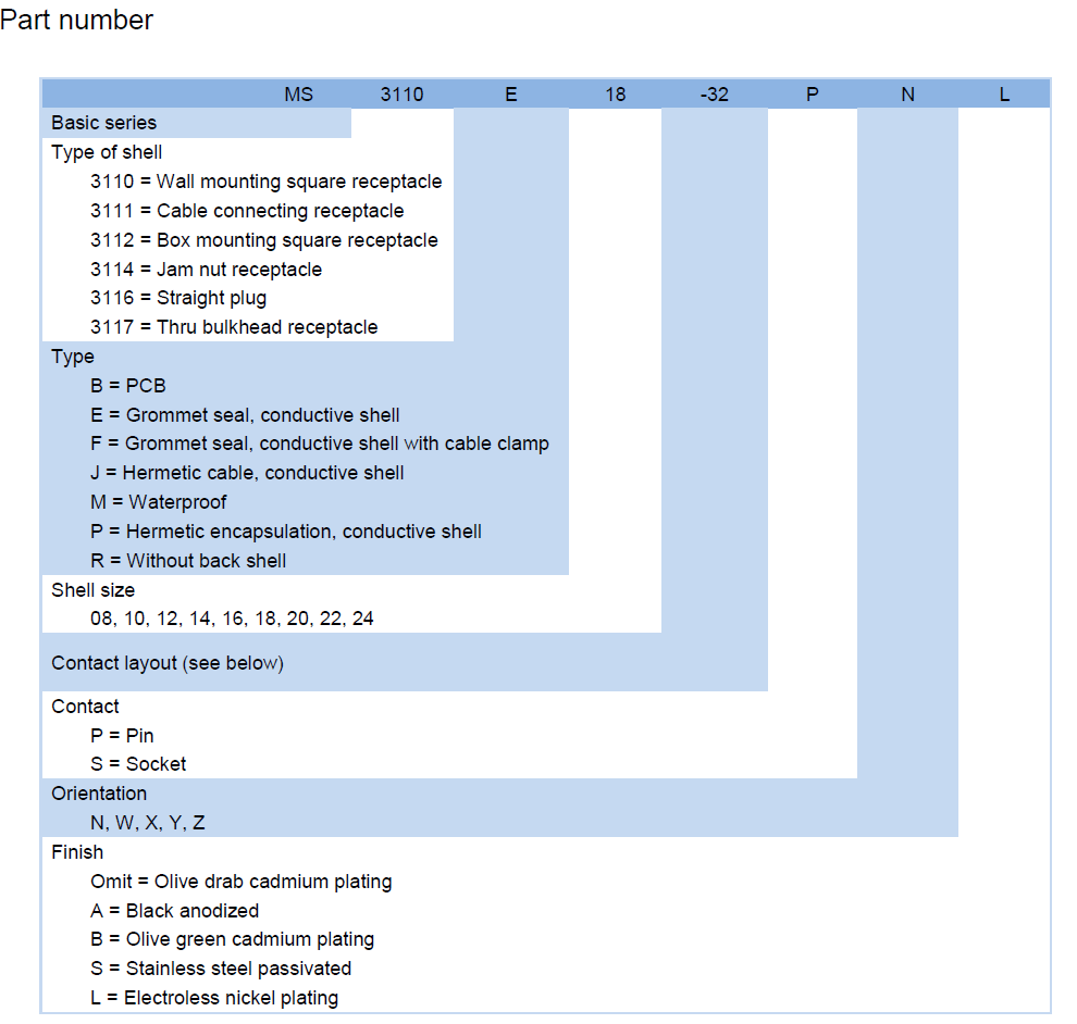
| Code element | What it sets |
| Basic series | MS — MIL-DTL-26482 Series I |
| Shell style | 3114 — jam nut receptacle |
| Type / rear sealing | E — grommet seal, conductive shell |
| Shell size | 08 — shell size 08 |
| Contact layout | 02 — insert arrangement, which fixes contact count and contact size |
| Contact gender | P — pin contacts |
| Key orientation | N — normal key position |
| Finish | B — olive green cadmium plating |
Target Applications
- Avionics and flight-control bays: this MIL-DTL-26482 aerospace connector is the fixed interface on instrument racks, control units and flight-line test boxes, where the cable assembly is built at a bench and mated on the aircraft.
- Ground vehicle electronics: hull wiring in combat and transport vehicles, where cables run past heat sources and the coupling has to stay sealed through fording, dust and continuous vibration.
- Naval and shipboard equipment: deck boxes, mast wiring and interior subsystems where salt spray and washdown decide how long a connector lasts.
- Undersea sensors and buoy systems: pressure housings and communication buoys, where the mated pair is immersed and the rear grommet does the work of keeping the contact chamber dry.
- Rugged industrial plant: oil, gas, mining and heavy machinery control cabinets. Specified as an environmentally sealed circular connector, it suits cabinets that are hosed down or that live outdoors all year.
- Test equipment and depot benches: cable adapters and test jigs where one receptacle is mated and unmated far more often than it ever would be in service.
Technical Specifications
- Precision-machined contacts with gold over nickel plating: the plating stack keeps contact resistance low and repeatable, so signal levels and voltage drop stay consistent instead of drifting as the joint beds in.
- Up to 5 A per contact: enough for control circuits, sensor supplies and small actuators on a vehicle or airframe wiring loom, shared across the contacts the chosen layout provides.
- Up to 500 V working voltage: covers the low-voltage distribution and signal wiring found in most airframe, vehicle and industrial control installations.
- Contact stability under movement: the assembly is built as a vibration resistant circular connector, so contact interfaces stay seated and resistance does not wander while a platform is running or a vehicle is on the move.
- EMI/RFI shielding to MIL-STD-461: the conductive shell and plated body give the interface shielding performance for densely wired panels where signal and power lines run close together.
- Insert geometry fixed by the ordering code: because layout and contact gender are written into the number, a replacement behaves electrically like the part it replaces and the wiring loom does not need re-checking.
| Parameter | Specification |
|---|
| Shell material | Aluminium alloy |
| Shell finish | Cadmium plating to MIL-STD-171, olive green (B code) |
| Contact plating | Gold over nickel |
| Contact type | Crimp, pin (P code) |
| Insert material | Chemical-resistant thermoplastic |
| Contact rating | Up to 5 A per contact |
| Voltage rating | Up to 500 V |
| Temperature range | -65 °C to +175 °C |
| Sealing | IP68, protection to 10 m depth, mated pair |
| Mating cycles | 500 minimum |
| Shielding | EMI/RFI shielding to MIL-STD-461 |
| Coupling | Bayonet, keyed |
| Mounting | Jam nut receptacle, shell size 08 |
| Contact layout | 02 arrangement |
Ordering and Delivery
- Order by the full part number, or by the four details that define it: shell style, shell size and layout, contact gender and finish.
- Add the contacts to the order: tell your MIL-DTL-26482 connector supplier whether you need loose crimp contacts and how many, so the assembly bench is not left waiting on a second shipment.
- Say if you need the mating plug: it can ship with the receptacles so the pair arrives together and the cable half is not built against a guess.
- Flexible MOQs: quantity is matched to what the job actually needs, so a single replacement receptacle and a full build quantity are both workable.
- Stable global delivery: orders ship on a regular schedule to customers across Europe, the Middle East and other markets, and the delivery date is confirmed when the order is placed.
- Lead time depends on whether the item is a stock line or built to order — confirm the current lead time for your quantity with your sales contact before you commit to a build date.
- Packing follows the build: if the receptacles are going into a kit for a specific assembly station, say so when ordering so the packing suits the way your bench issues parts.
- Documentation: state up front what your quality team needs to receive with the goods, so it can be prepared alongside the order rather than requested afterwards. Most of what a connector costs a program is decided after it is fitted, not at the point of purchase. Three things drive that: how often the part has to be replaced, how long the wiring lasts, and how much engineering time goes into making a second source fit. A 500-cycle coupling on a plated metal shell stretches the service interval, which shows up as a smaller spares holding and fewer unscheduled removals over a platform's life. Because the part is built to the Series I interface rather than a proprietary one, an existing cable assembly does not have to be re-drawn around it, and hardware already sourced for the standard — plugs, backshells, contacts — stays usable. A question about an insert arrangement, a plating code or a contact tool reaches the people who build the part, instead of a sales desk that has to ask someone else and come back tomorrow. The practical test of all of it is your own incoming inspection: order against the part number, check the plating and the contact seating, and measure the first article against the drawing. If it does not match, no value argument survives — which is why we would rather be measured against the specification than against a price list.
Technical Support & Model Matching
Selecting the right connector is rarely a one-line decision. Send us your drawing, part number or a sample, and our engineering team will confirm the matching shell size, contact arrangement, coupling and mounting style, cross-reference discontinued or alternate part numbers, and advise on sealing and flange options for your environment. We also help troubleshoot fit, mating and signal problems, and give installation and commissioning guidance so your line stays up. As a direct manufacturer, our answers come from the people who build the parts — from first enquiry through after-sales support.
FAQ
Does the IP68 rating apply when the connector is unmated?
No. The IP68 military circular connector rating describes the coupled assembly: this receptacle, its mating plug, and the coupling fully locked. Unmated, the rear grommet still closes around the wires, but the front contact chamber is open to air and debris, so keep the receptacle covered during build and transit. If your process leaves a panel connector open for long periods, tell us and we will talk through the options in the range.
Can I buy the mating plug and the loose contacts at the same time?
Yes. The range covers plugs, receptacles and loose crimp contacts, so a complete cable assembly can be kitted in one order. Give your mil-dtl-26482 connector supplier the shell size, the contact layout and the contact gender of each half, and the plug will be matched to this receptacle rather than chosen by eye. If you are re-terminating an existing cable, tell us the wire gauge so the contacts and the rear grommet suit it.
Can this replace the connector already called out on our drawing?
In most cases yes, provided the four defining details match: shell size, contact layout, contact gender and key orientation. This military circular connector OEM part is built to the MIL-DTL-26482 Series I interface, so any Series I plug built to those same four details mates to it regardless of who built the plug. Send the old part number or the drawing and we will confirm the match before you commit a build to it.
Is it suitable for outdoor and marine equipment, not just aircraft?
Yes — deck hardware, communication buoys, outdoor cabinets and oil and gas plant are all normal work for this pattern of environmentally sealed circular connector. Two details decide how well it lasts there: the plating, because salt exposure attacks the shell, and the panel joint, because that is the seal path the connector itself does not control. Tell us the exposure and we will confirm the right finish code for it.
Should we use this or a Series III connector on an aerospace wire assembly?
It comes down to the interface your drawing already specifies. The MIL-DTL-26482 aerospace connector is the smaller bayonet-coupled Series I pattern, and it is the right choice where the wiring, the panel cut-out and the mating plug are already built around Series I. Series III is the later, higher-density pattern and belongs where that interface is called out. Switching series means changing both halves and the panel, so mid-program the series on the drawing is usually the cheaper route.
Will the coupling stay tight on a vibration-heavy installation?
A correctly mated bayonet coupling is a vibration resistant circular connector by design: it locks instead of relying on friction, and the keying keeps the two halves aligned. What causes problems is partial mating — a coupling turned most of the way but not locked will feel secure and will not hold. Check that the coupling has travelled to its locked position at build, and again after the first run on a new cable assembly. If your platform has a defined vibration profile, share it and we will confirm this is the right part for it.