Product Introduction
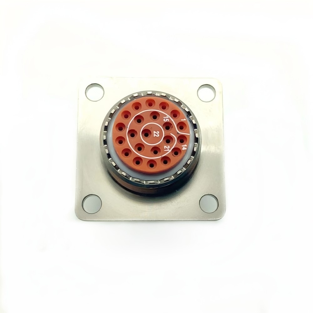
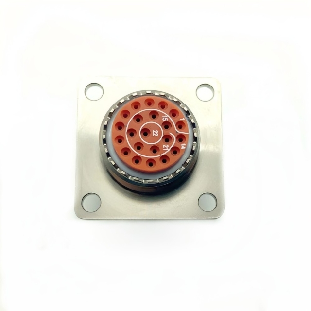
The MS27497T12F35PB connector is a MIL-DTL-38999 Series II wall-mounting square flange receptacle in shell size 12, built with a threaded rear interface for a backshell and fitted with crimp pin contacts. It is the bulkhead half of a cable assembly: the square flange bolts to a panel or frame, the bayonet coupling takes the mating plug, and the sealed shell keeps moisture and dust away from the contact chamber.
Cable assemblies that leave a protected interior are where this part belongs — the run from an avionics bay to an external antenna, the cable that crosses a vehicle firewall, the lead that goes up a mast. Buyers specifying a MIL-DTL-38999 Series II connector for those runs need the panel cut-out, the mating plug and the wiring schedule to stay exactly as they are, and this receptacle follows that interface instead of asking for a redesign.
The shell is finished in electroless nickel, the contact chamber is sealed, and each unit is checked before packing for the seal integrity and vibration performance expected of a vibration resistant circular connector.
MIL-DTL-38999 Series II Interface
- Bayonet coupling. A short twist seats and releases the plug, so a connector on a crowded bulkhead can be serviced without tools and without disturbing the wiring beside it.
- One family, several mounting styles. MS27497 is the rear-mounted wall receptacle; the same series also covers plugs, front-mounted wall receptacles, box receptacles, jam-nut receptacles and shielded plugs, so a cable assembly can be built from one interface family end to end.
- Sealed by design. Series II parts are environmental connectors: the coupling interface, the rear wire entry and the insert-to-shell joint are all sealed, which is what lets the same shell serve as a waterproof military circular connector inside a bay and on an exposed panel.
- Field-terminated contacts. Crimp contacts are terminated with standard tooling and inserted from the rear, so a damaged circuit can be re-terminated at a bench rather than replacing the cable assembly.
- Keyed against cross-mating. Identical shells can be ordered in different key positions, so two adjacent receptacles cannot be plugged into the wrong cable assembly.
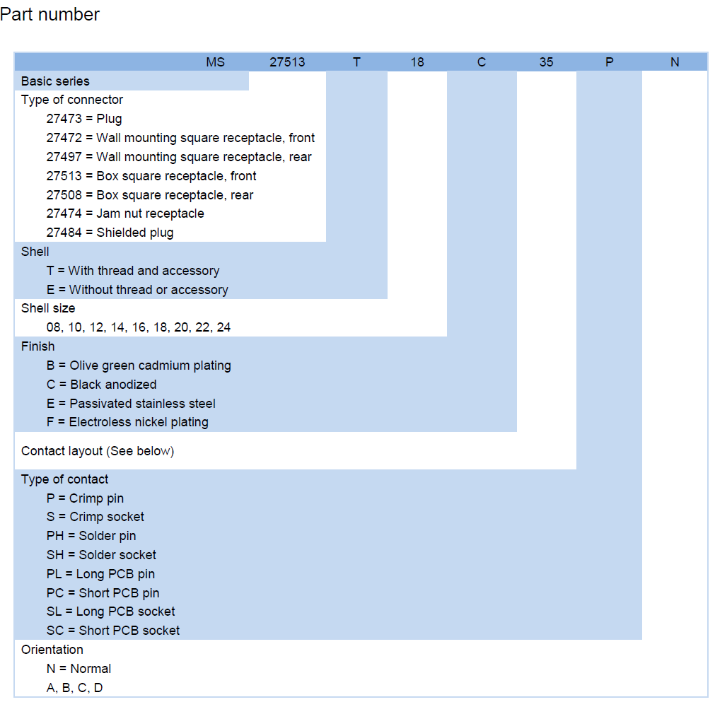
- Readable part numbering. The marking on the shell carries the mounting style, shell size, finish, contact layout, contact type and key position, which is enough to order a replacement from the old part itself, since the marking follows the scheme a MIL-DTL-38999 connector manufacturer builds to.
Harsh-Environment Durability
- Vibration. The shell is qualified across the band that matters on aircraft and vehicles, from the low-frequency movement of a chassis mount up to the high-frequency buzz of engine-driven accessories. A vibration resistant circular connector holds contact resistance steady instead of letting the contacts fret against each other.
- Shock and impact. Drop and impact loads are covered by the same qualification: the insert stays seated and the coupling stays locked when the platform takes a hard landing or a kerb strike.
- Salt fog. The plated shell and sealed joints resist salt-fog attack, the failure mode that quietly destroys unprotected connectors on deck and on winter roads.
- Temperature. The part runs from deep cold to the heat soak of an engine bay; thermal cycling is where the seals and contact retention of an aerospace circular connector are really proven, not at a single steady temperature.
- Electromagnetic interference. The metal shell forms a continuous shield around the contact bundle, and the contact system keeps impedance stable with low insertion loss, so signal integrity survives a high-interference environment.
- Mechanical wear. The coupling and keyway take the handling load rather than the contacts, so repeated mating does not degrade the electrical path.
- Interface seal. A resilient face seal closes the gap between plug and receptacle the moment the coupling locks, so the contact chamber is isolated before moisture can reach the pins.
- Rear wire seals. Each wire passes through its own seal at the back of the insert. The seal grips the insulation rather than the conductor, which is what keeps water out of a cable bundle that is washed down or briefly immersed.
- Body seal. A seal between the insert and the shell closes the path moisture would otherwise take around the outside of the contact block.
- Flame-retardant materials. The insert and seals use materials specified to MIL-STD-810 for flame retardancy, so an electrical fault inside the shell does not turn the connector into a fire path.
- Sealing that survives mating cycles. The interface barrier sits in the coupling face rather than on the contacts, so routine mating and unmating does not wear away the layer that protects the pins — which is the weakness of a waterproof military circular connector built around a single gasket. A quick-disconnect coupling supports field servicing. Color-coded inserts simplify assembly and troubleshooting.
Crimp Pin Contact System
Contacts in the MS27497T12F35PB connector are crimp pin type, which means the wire is terminated at a bench with a standard crimp tool and the finished contact is pushed into the rear of the insert until it locks. That is the arrangement most cable assembly shops prefer: the crimp is made and inspected away from the shell, and a contact damaged in service can be cut out and replaced without touching the rest of the cable assembly.
The contacts are gold plated. Gold does not oxidise in storage or in humid air, and it keeps contact resistance low and repeatable over thousands of mating cycles, which is why it is the default plating on mil-spec signal contacts rather than a cost option.
The size 12 shell with the 35 contact layout carries more circuits than the compact shell 08 version of the same MIL-DTL-38999 Series II connector, which is often the reason a cable assembly is moved up to this size instead of adding a second feed-through.
Two features protect the electrical path during assembly. Polarised keying means the plug can only enter one way, so a technician working by feel cannot force the coupling onto the wrong key position. Colour-coded inserts identify the contact arrangement at a glance, which speeds up inspection and fault finding on a panel full of similar connectors.
Because this is the pin half of the pair, it mates with a plug carrying socket contacts — worth noting when the part number is being copied from the connector at the other end of the cable.
- Inspect the coupling face and the interface seal before mating; a grit-covered seal is the most common cause of a leak that only shows up weeks later.
- Wipe the keyway and the coupling ramps clean, and check that the key is not burred or flattened.
- Align the key with the keyway and push the plug straight in until it seats. Do not use the coupling ring to drag the plug home.
- Twist the bayonet coupling until it locks, then try the plug gently to confirm it is fully seated rather than assuming it.
- On removal, fit the protective cap on the receptacle and stow the plug with its own cap; a connector left open on a vehicle is where most field failures begin.
- When a circuit fails, replace the crimp contact from the rear rather than the whole receptacle — the shell, the seal and the keyway usually have plenty of life left in them.
- Repair at bench level. A failed circuit is fixed by replacing one crimp contact from the rear; the shell, the seal and the rest of the wiring stay exactly where they are.
- Visible wear. Seal and coupling condition can be judged at inspection, so a seal is scheduled for replacement at a convenient interval instead of failing mid-deployment.
- Spares that cannot be mixed up. Because the keyed interface will not accept the wrong plug, a spare receptacle with the right key can only be fitted to its own wiring assembly — a real advantage when stores hold several similar part numbers.
- Long service intervals. Where a platform is serviced only every few years, a connector that needs no attention between services is worth more than one with better headline numbers.
- Standard tooling. Crimp contacts use the tooling a depot already has, so supporting the part does not mean buying a new kit.
- Fewer wiring assembly replacements. Most downtime attributed to a connector ends with a whole wiring assembly being changed; re-terminating a single contact avoids that.
Design Advantages
Four details decide whether this is the right receptacle for a given panel.
Mounting. The rear-mounted square flange fixes from behind, so an existing four-hole cut-out can be reused and the outside face stays clean. If the panel is already drilled for a front-mounted wall receptacle, the front version of the same shell is the correct part instead.
Contact gender. This is the pin half, so it mates with a plug carrying socket contacts. Teams occasionally order the wrong gender because the part number was read from the mating plug rather than from the receptacle on the panel — copy the marking on the part you are replacing.
Keying. Position B is an alternate key. It exists so that two receptacles with the same shell size and contact layout can sit side by side without being interchangeable. If the cable assembly expects the normal key, specify the N version rather than forcing a B to fit.
Finish. Electroless nickel gives a hard, conductive, corrosion-resistant surface that takes repeated handling without flaking. If the drawing calls for olive green cadmium, black anodised or passivated stainless steel, those exist in the same series — match the finish to the drawing and the environment, then confirm it in writing on the order.
On a typical connector pair the receptacle is the fixed half and the plug is the half that travels with the cable. This one mounts from the rear of the panel, which keeps the flange and its fixings on the inside face while the coupling end stands proud where an operator can reach it. That matters where the outside of the equipment has to stay flush, or where there is no room to swing a tool behind the panel. Three priorities shape the design. Environmental resilience comes first: shell, seals and finish are chosen so that shock, vibration, moisture and temperature swings never reach the contacts. Secure electrical performance comes second: contacts are held at a controlled insertion depth so resistance stays stable through thermal cycling, and the metal shell provides a continuous conductive path around the contact bundle. Long-term durability comes third: the parts that wear — coupling, keyway and seals — are the parts that are easiest to inspect. In an aerospace circular connector programme, that combination matters most where a cable run crosses a pressure boundary or a firewall. The receptacle is the part that has to hold its sealing and its contact alignment for the life of the airframe, not just for the first mating cycle.
The strongest argument for a Series II receptacle is usually the wiring it has to fit. Where a platform has been in service for decades, the panel cut-out, the mating plug and the wiring schedule are fixed, and any change to them means a modification programme rather than a repair. This part follows the MIL-DTL-38999 Series II connector interface, so the existing plug, the existing keying and the existing mounting pattern remain valid. That also makes it a practical answer to obsolescence. When an original part number becomes hard to obtain, the options are a redesign or a custom MIL-DTL-38999 connector built to the same interface; supplied with documentation, the latter is the cheaper of the two, provided the drawing is checked line by line first. Two details deserve that check before a legacy order is released. Key position: an alternate key such as B looks identical to the normal key until the plug refuses to enter, so compare the marking on the old part with the new one. Contact gender: receptacles and plugs are sold in both pin and socket versions, and a cable assembly rebuilt more than once may no longer match its original drawing. Both take a minute to verify against the old part.
Target Applications
The MS27497T12F35PB connector goes into systems where a failed connection is not a nuisance but an incident: flight controls, radar, tactical vehicles, submarine electronics. The common thread is that the connector is the cheapest part of the assembly and the most expensive one to reach, so it is specified for the life of the platform rather than for the current maintenance interval. The three environments behind most orders behave differently. In an aerospace circular connector installation the enemy is altitude and thermal cycling: low pressure, wide temperature swings and vibration from engines and airflow. In ground and vehicle service it is shock, dirt and constant low-frequency vibration. At sea it is chloride — salt fog, deck-level moisture and condensate that finds every unsealed joint. A sealed, keyed, plated receptacle answers all three, but the finish and the mounting style change with the job. Beyond defense and aerospace, the same shells turn up in industrial systems: test rigs, ground support equipment, heavy machinery, anywhere a buyer wants a connector that will not become the weak point in an otherwise robust machine.
- Flight control and actuation. Actuator runs carry continuous vibration and thermal cycling; the keyed, sealed interface keeps contact resistance stable where a loose contact would appear as a control fault.
- Engine monitoring. Sensor cable runs routed close to hot sections rely on the temperature capability of the insert and shell rather than on extra insulation around the cable.
- Airframe feed-throughs. Rear mounting puts the flange and its fixings inside the structure and leaves a flush face outside — the arrangement most airframe panels are cut for.
- UAV and satellite subsystems. Where a cable assembly is built, tested and then left alone for a long time, gold-plated crimp contacts and a sealed shell cut down the number of things that can drift. Ground and vehicle programmes ask for this receptacle for three jobs: radar and sensor racks, tactical vehicle wiring, and communications equipment. All three share a maintenance reality — the equipment is worked on in the field, often at night, often by a technician wearing gloves — so the parts that matter are the ones that cannot be assembled the wrong way. The keyed interface, the bayonet coupling and the colour-coded insert all exist for that moment. Vibration is the other constant. A tracked vehicle sends a broad, low-frequency shake into every bracket on the hull, and a wheeled vehicle adds road buzz on top of it. As a military circular connector supplier we see the same pattern in every programme: the connectors that fail are almost never the ones that were undersized electrically — they are the ones that were allowed to work loose or take in water. That is the failure mode this shell is designed to remove.
- Deck-level fittings. Salt fog and spray attack every exposed surface; the plated shell and sealed joints are what keep chloride away from the contacts.
- Naval vessel electronics. Long refit cycles mean a connector may sit mated for years and then be disturbed once; the coupling and the seal have to work on that first movement after a long rest.
- Masts, winches and deck machinery. Continuous movement and washdown; rear mounting keeps the fixings inside the housing where they are not directly exposed.
- Offshore and harbour equipment. The same shell appears on dockside power and control cabinets, where buyers choose a mil-spec connector because the commercial alternative keeps failing in the salt air.
Key Specifications
| Series | MIL-DTL-38999 Series II |
| Connector type | Wall-mounting square flange receptacle, rear mount |
| Shell size | 12 |
| Coupling | Bayonet, quick disconnect |
| Shell finish | F — electroless nickel plating |
| Contact type | P — crimp pin |
| Contact layout | 35 |
| Key position | B — alternate key |
| Sealing | IP67 |
| Operating temperature | -65 °C to +200 °C |
| Vibration | 10–2000 Hz |
| Shock | 100 G |
| Rear interface | Threaded, accepts rear accessory |
Competitive Advantages
- Built in-house. As a MIL-DTL-38999 connector manufacturer we machine, assemble and test on our own floor, so the people answering a question about a shell size or a key position are the same people who built the part.
- Configurations to drawing. Send the specification — contact type, keying, finish, mounting style — and we build a custom mil-dtl-38999 connector to it rather than pushing you toward the nearest catalogue item.
- Every unit tested. Environmental sealing and vibration performance are checked on each connector, not on a sample pulled from the batch.
- Drawing-to-test control. Each batch is built to the released drawing and checked against it before packing, which is what keeps a second order identical to the first.
Ordering and Delivery
- Check the part against your drawing first: shell size, contact layout, key position, finish and contact type should all match before anything is quoted.
- Say whether you need the receptacle on its own or together with crimp contacts and a rear accessory, so the quotation covers a complete assembly rather than a shell that arrives incomplete.
- Tell us the quantity and the delivery date the programme needs; stock items and made-to-order quantities are scheduled differently and the date is confirmed on the quotation.
- Agree the documentation package — certificates of conformity, test reports or anything else your receiving inspection requires.
- Confirm packing, shipping terms and payment terms with your sales contact when the quotation is issued; these are set per order and confirmed in writing.
Technical Support & Model Matching
Choosing the right shell size, contact arrangement, keying and coupling for a cable assembly is where most ordering problems start, so our engineers work through it with you before anything is shipped. Send a part number, drawing or photo of the connector you are replacing and we will cross-reference it against our MIL-DTL-38999 range and confirm the closest equivalent. After delivery we stay available for mating and installation guidance, wiring questions and fault finding, and we are glad to quote bulk orders and custom designs.
Reliability in a connector is rarely about one dramatic failure. It is about contact retention staying inside tolerance after a thousand thermal cycles, a seal that still seals after a hundred matings, and a keyway that has not worn enough to let the plug rock. Those are the things the Series II specification sets out to control, and they are the things we build and test to. As a military circular connector supplier we would rather tell a buyer what a part will and will not do than let a drawing number imply more than it should. This receptacle is built to MIL-DTL-38999 Series II. If your programme needs a particular qualification listing or a third-party approval, say so at the quotation stage and we will confirm what can be provided — better to settle that before a purchase order than at receiving inspection. What every unit does carry is design margin: sealed interfaces, retained contacts, a plated shell and a coupling that locks. Those are checked before packing, and the results can travel with the shipment.
- Traceable production. Every run is built against a released drawing, so the part in the box can be traced back to the specification it was made to.
- Documentation per run. Certificates of conformity and test reports can travel with the shipment; tell us at quotation stage which documents your receiving inspection needs and they are prepared with the order.
- Repeatable supply. As a MIL-DTL-38999 connector manufacturer we hold the tooling and the process, so a repeat order placed years later is the same part rather than a re-engineered one.
- Series breadth from one source. Series II and Series III receptacles, plugs, contacts and rear accessories come from the same production floor, which keeps a programme with mixed connector types on a single purchase order.
FAQ
What does the 'B' at the end of MS27497T12F35PB tell me?
It is the key position. Series II shells are available with a normal key, marked N, and with alternate keys A, B, C and D. An alternate key rotates the keyway so that two receptacles with the same shell size and contact layout cannot be plugged into each other's cable assembly. Position B is therefore a deliberate choice on this part: check that your mating plug carries the matching key before the order is released, because a plug keyed N will not enter a B receptacle.
Will this receptacle mate with the plug already on my wiring?
Yes, provided the plug on your cable assembly is a Series II plug of the same shell size and insert arrangement — and the quickest way to settle it is to read the marking on the plug shell, then compare it line by line with the receptacle's marking. If the plug's marking is worn, painted over, or carries a legacy number that no longer appears in catalogues, work from the wiring drawing instead: the drawing's mating-connector field should name a Series II plug, and the insert arrangement, shell size and key position on that drawing should agree with the receptacle you are ordering. Check the contact gender recorded for each half as well, because the two sides must carry opposite contacts and a drawing that lists the receptacle as the pin side implies a socket-contact plug. Confirm the plug is an environmental, bayonet-coupling plug of the same class — a non-sealed plug or one with a different coupling style will not lock and seal against this shell — and note that a Series I or Series III plug will not mate with a Series II receptacle even when the shells look alike. Where the original assembly is old enough that the plug number has been superseded, send us the plug marking or a clear photo of the insert face with your enquiry and we will cross-check it against the Series II interface before you commit to a quantity. A bench trial-fit of one pair is still worth doing before the balance of the order is released.
How does the contact chamber stay dry in washdown and salt air?
Three seals do the work: a face seal at the coupling interface, individual seals around each wire at the rear, and a body seal between the insert and the shell. Together they close every path into the contact chamber, which is what allows a waterproof military circular connector to be used on a deck fitting and inside a hull with the same shell. The plated finish then handles the outside of the shell, where salt fog attacks first.
Can the receptacle take engine-mounted or vehicle-mounted vibration?
Yes. It is built as a vibration resistant circular connector: each contact is retained independently in the insert, the bayonet coupling locks instead of relying on friction, and the shell is qualified across the vibration band used for airborne and vehicle equipment, with shock capability to match. On an engine mount, support the cable bundle close to the connector so the cable's own weight is not carried by the coupling.
Can you supply a custom mil-dtl-38999 connector built to our drawing?
Yes. Send the drawing or the configuration you need — shell size, contact layout, contact type, finish and key position — and we build it as a custom mil-dtl-38999 connector rather than matching it to the nearest catalogue item. That is the usual route when a drawing calls for a finish or a keying that is not the standard build.
If my wiring needs more circuits, should I move up a shell size?
Usually, yes. Within the same receptacle family a larger shell takes a denser contact layout — the size 12 shell used here carries more circuits than the compact size 08 version. Moving up gives you the extra contacts without adding a second feed-through, but it also changes the panel cut-out, so check the mounting dimensions against the panel before you decide.