Product Overview
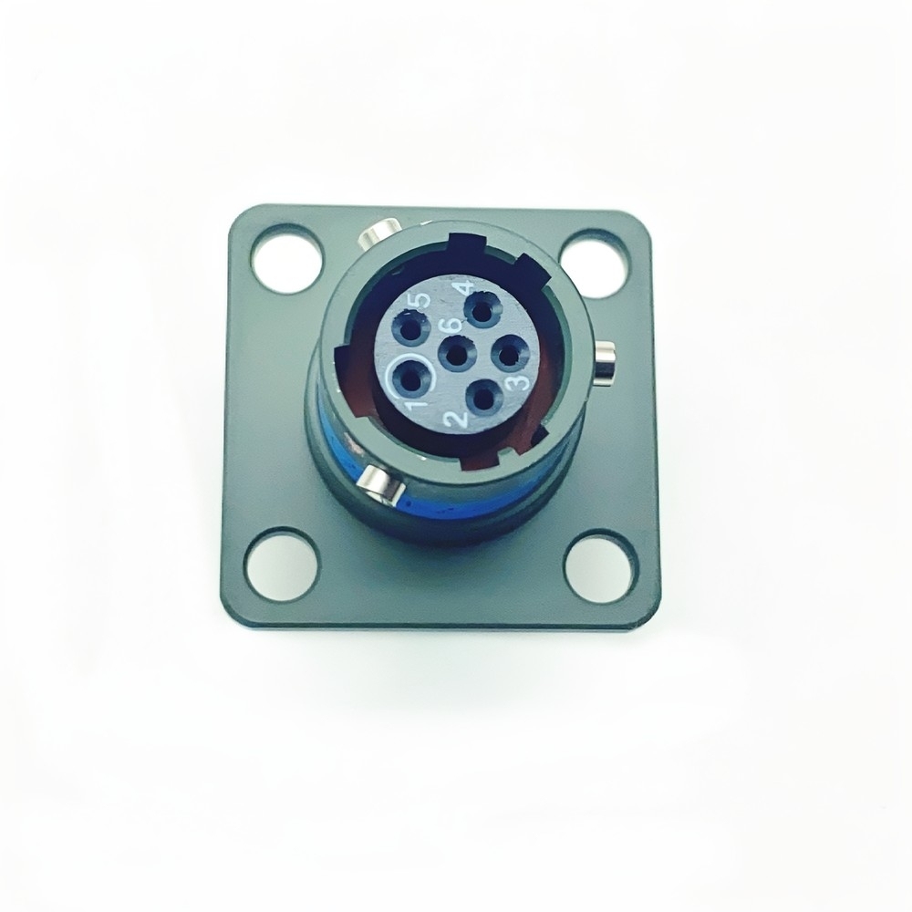
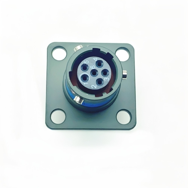
The MS27497T08B35SN is a wall-mounting square-flange receptacle from the MIL-DTL-38999 Series II family, built on a compact shell size 08 body. It carries crimp socket contacts in a numbered insert, a threaded rear interface for an accessory, and an olive green cadmium finish. The flange fastens to a bulkhead or chassis panel while the cable bundle is dressed in from behind, which is what makes this a panel mount circular connector rather than a free-hanging plug. Where a shell 08 mil-dtl-38999 series ii connector earns its place is in dense wiring. The small body keeps the footprint on the panel tight, so more feedthroughs fit into an avionics bay, a communications rack or an instrument enclosure. Mechanically it is the fixed half of a cable-to-equipment link: the receptacle stays bolted to the chassis, the plug travels with the cable bundle, and the two separate only when the coupling is released. Once mated, the interface is sealed, so washdown, condensation and driving rain stay away from the contacts.
Advanced Contact System
Gold plating is doing a specific job here. It keeps contact resistance low and stable, and it does not build the resistive oxide film that tin or bare copper develops in humid, salty air. A mated pair that has sat on a vehicle for years still separates cleanly and re-mates without polishing base metal back to life.
The contacts on this part are crimp sockets. The wire is crimped on the bench with a calibrated tool, the contact is pushed into its numbered position on the insert face and held by the retention clip, and the whole operation is repeatable by any technician with the right crimper. If a circuit is damaged, one contact and one wire end are replaced — not the connector, and not the wiring loom.
The numbered insert is the other half of that story. Fault-finding starts from a circuit number rather than a process of elimination, so a continuity check or a re-termination can be done from a schematic without pulling the bundle apart on the bench.
Polarised keying stops a plug from being forced into the wrong receptacle. This part carries normal keying, and A, B, C and D key variants exist elsewhere in the range for the case where two identical shells sit side by side and must never be interchanged. Match the key letter, not just the shell size — on an oem military circular connector the letter is part of the part number, not a preference.
Triple-Seal Environmental Protection
- Interfacial seal. A resilient face seal compresses between the receptacle and the plug the moment the coupling is made, closing the path across the contact face before the shells are fully seated.
- Individual wire seals at the rear. Each wire passes through its own seal at the back of the insert, so moisture cannot track along a conductor into the contact cavity even where the cable jacket has been nicked or opened during routing.
- Body and accessory seals. Seals between the shell components close the connector itself, and the rear thread takes an accessory grommet or backshell seal so the protection does not stop at the flange.
- Flame-retardant material selection. Materials are selected against MIL-STD-810 flame requirements, which matters where the connector sits near power switching equipment rather than in a benign rack.
- Sealing and screening are solved together. A joint that keeps water out but screens poorly is no help in an EMI shielded military connector, so the shell-to-shell contact area is treated as part of the environmental design rather than an afterthought.
- A quick-disconnect coupling supports field servicing, and color-coded inserts simplify assembly and troubleshooting.
MIL-DTL-38999 Series II Interface
MIL-DTL-38999 is the specification that governs circular connectors for military and aerospace service, and Series II is one branch of it. What the standard fixes is the part that matters most in a repair or a re-build: the shell and interface geometry, contact retention, the sealing classes and the environmental envelope. A receptacle built to the series mates with plugs built to the same series and shell size, whoever made either half — which is why a bayonet military circular connector from one production run still couples to a plug from another.
The practical consequence is backward compatibility. If a legacy assembly already uses shell size 08 and this contact layout, the receptacle drops into the same panel opening and the same cable length. No new bracket, no re-drawn loom, no requalification of the mating interface. That is the difference between a replacement and a redesign.
Coupling style is a separate decision from the series itself. A threaded coupling military connector resists back-off under sustained vibration; a quarter-turn coupling is faster to break in a tight bay. Tell us which plug you are keeping in service and, as a military circular connector supplier, we will confirm that the receptacle you order presents the right interface to it.
Installation and Field Servicing
- Confirm the interface before the panel is cut. The mounting code matters: 27497 is the rear wall-mounting square receptacle, while the front-mounting 27472 presents the same shell differently. Check the shell size, layout and key letter at the same time, because none of them can be corrected once the opening is made.
- Fasten the flange square to the panel. Seat the receptacle against the opening and tighten the flange fasteners evenly so the body does not distort and pull the insert out of alignment.
- Crimp, insert and tug-test each contact. Push every socket contact into its numbered cavity until the retention clip engages, then pull back gently on the wire. A contact that has not clicked home will push out again on the first mating cycle.
- Mate a quarter-turn plug with the keys aligned. Where the cable assembly uses a bayonet military circular connector plug, align the keys, push straight, and turn until the detent engages. Never use the coupling to draw the two halves together.
- Run a threaded coupling down by hand first. Where the mating half is a threaded coupling military connector, start the thread by hand, confirm it is not cross-threaded, then finish to the coupling's seating torque.
- Fit the accessory and clamp the wire bundle. Screw the backshell or strain relief onto the rear thread so the bundle is supported behind the connector and the screen is terminated to the shell if you are relying on the shielding figure.
- Service from the panel face. Release the coupling and unscrew the accessory, and the insert face is accessible without disturbing the panel mounting. Damaged contacts can be replaced at the bench and the receptacle put straight back into service. As a direct military circular connector supplier, we eliminate middleman markups to offer competitive volume pricing for aerospace and defense procurement. We support flexible MOQs and stable global delivery to keep your supply chain on schedule. The connector is engineered as a system-critical enabler for applications where failure is not an option, and its adherence to MIL-DTL-38999 Series II underscores a commitment to excellence for engineers prioritizing longevity, safety, and performance.
Target Applications
The same shell 08 receptacle turns up in three quite different service environments, and it is worth being clear about which one you are buying for, because it changes what you should verify first. In an aircraft it is the temperature and altitude envelope plus EMC that decide. On a vehicle it is shock and sustained vibration. At sea it is salt fog and standing moisture. A connector that is comfortable in one of those is not automatically comfortable in the other two, and the verification you ask for should follow the environment rather than the headline figure.
Below the defence sectors, the same part appears in industrial equipment where a mil-spec interface has been adopted for reliability — test rigs, ground support equipment, broadcast and telecom racks — usually because the equipment has to survive the same handling and weather as the platforms it supports.
- Avionics bays. Rack-mounted line-replaceable units are where the compact body pays for itself, because a bay that is already full of feedthroughs has no spare panel area for a larger shell. A mil-dtl-38999 series ii connector keeps the interface defined while the enclosure keeps shrinking.
- Flight control and actuation. Control-surface electronics run close to hydraulic and electrical noise sources, and the wiring is often routed past power feeders. The screened shell keeps induced noise off the low-level signal pairs sharing the same connector.
- Engine monitoring. Probes and sensors near the hot section see the top of the temperature range on soak-back after shutdown, which is where the +200 °C end of the envelope is actually used.
- Communications and datalink equipment. Transmitters and receivers frequently share an enclosure, so the connector has to hold its screening where the radio sits inches away from the wiring it is not supposed to talk to.
- Ground support and test equipment. The same receptacle is used on rigs that are plugged and unplugged far more often than the aircraft itself, which makes the contact retention and the coupling wear the deciding factors.
Ground and vehicle installations ask the least glamorous work of this receptacle. Radar shelters, tactical vehicle harnesses and man-portable communications sets run their connectors through repeated mating, dirty handling and continuous vibration, usually with the panel buried behind other equipment that nobody wants to move. Vibration duty is the deciding factor here more often than temperature. A hull-mounted bracket feeds a broad spectrum into the shell, and a coupling that creeps shows up later as intermittent contact rather than as a clean failure — the most expensive kind of fault to trace on a vehicle. That is why a bayonet military circular connector is common on harnesses a technician has to break in the field with cold hands and limited access, while a threaded interface goes on the joints that are made once and left alone. Communications equipment adds a second constraint. The same enclosure often holds the radio and the connector, so screening and sealing have to be solved in one part, and the joint at the bulkhead becomes part of the RF path rather than just a mechanical fixing.
- Below-deck electronics. Naval vessel electronics sit in a warm, humid, salt-bearing atmosphere even when they never see spray directly, and condensation on a cold shell is the usual route to a wet contact cavity.
- Submarine systems. Cabin pressure and humidity control reduce the ambient aggression but make re-entry and servicing discipline critical, so a connector that can be opened and remated in place is worth more than one that cannot.
- Deck-level and topside fittings. Spray, driving rain and washdown all reach the interface, which is where the mated seal and the rear wire seals carry the load.
- Washdown routines. Cleaning crews do not always know what is behind a panel, so the connector has to tolerate a direct hose as well as weather.
- Mixed-metal bulkheads. Where a panel mount circular connector is bolted alongside stainless or galvanised hardware, the finish you choose affects how the assembly behaves in the long run — confirm the pairing with us rather than mixing codes on one panel without checking.
Specifications and Part Codes
- Small panel footprint. Shell 08 is the most compact body in this family, so a bulkhead carries more connectors before the panel runs out of room — often the difference between one more feedthrough and a redesign of the enclosure.
- Screening that holds at microwave frequencies. The shielding figure is measured where most designs fall apart: the shell-to-shell joint and the accessory thread have to stay continuously conductive, or the cable assembly itself becomes the antenna. That is what makes this an EMI shielded military connector rather than a well-sealed one.
- Built for sustained vibration. The assembly is tested across a 10–2000 Hz sweep and against 100 G shock, which is the duty seen on hull-mounted brackets, engine-adjacent panels and stores pylons.
- A temperature envelope with margin at both ends. -65 °C covers cold soak at altitude and in unheated storage, while +200 °C covers heat soak next to engines, actuators and power switching equipment.
- A rear interface that takes an accessory. The threaded rear, shown as the T in the part number, accepts a backshell, strain relief or conduit adapter so the cable assembly can be clamped and screened right up to the connector instead of hanging on the contacts.
- Corrosion protection for wet and salt-laden service. Olive green cadmium plating on the shell, together with gold-plated contacts, keeps the interface separable after long exposure to salt fog.
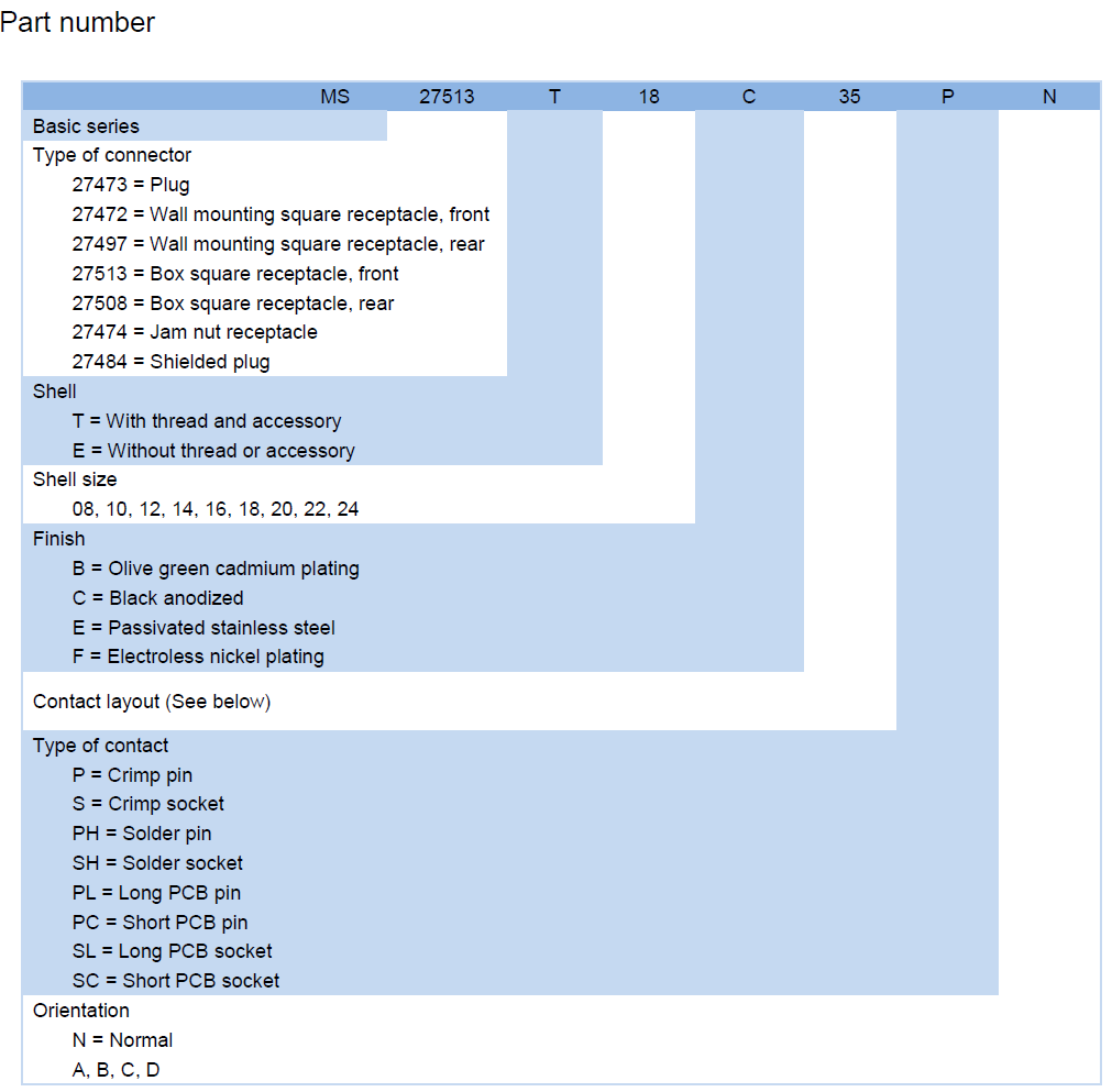
| Part number | MS27497T08B35SN |
| Basic series | MIL-DTL-38999 Series II |
| Connector type — 27497 | Wall mounting square receptacle, rear |
| Shell style — T | With thread and accessory |
| Shell size — 08 | 08 (the range also covers 10, 12, 14, 16, 18, 20, 22 and |
| Finish — B | Olive green cadmium plating |
| Contact layout — 35 | Arrangement 35, numbered on the insert face |
| Contact type — S | Crimp socket |
| Orientation — N | Normal keying |
| Sealing | IP67 when mated |
| Operating temperature | -65 °C to +200 °C |
| Vibration | 10–2000 Hz |
| Shock | 100 G |
| Shielding effectiveness | 65 dB at 10 GHz |
Ordering and Delivery
- If any of those needs to change, raise it at quotation rather than after the order is placed, because each one changes the part that gets built.
- Confirm the mating plug. Send the plug part number or a clear photo of the connector being replaced. We check shell size, key letter and coupling before anything ships — the cheapest place to catch a mismatch is before production.
- Confirm availability, minimum order quantity and lead time for the quantity you actually need. These vary by line and by whether the item is held in stock or built to order, so they are confirmed in writing with your quotation.
- Confirm documentation and packing. Tell us at enquiry if you need a certificate of conformance, test reports or a specific packing method for your warehouse or forwarder, and we will confirm what can be supplied with the shipment.
- Confirm commercial terms at quotation. Payment method, incoterms and shipping port depend on destination and order size, and are agreed in writing on the quote rather than assumed from a listing.
- Bulk, replacement and custom requirements. We supply volume orders, equivalent replacements for legacy part numbers and builds to your drawing. If you need a military circular connector supplier who can cover Series II and Series III from one source, send the full parts list and we will come back with a single offer.
- Certified reliability. Every unit is built to MIL-DTL-38999 Series II and goes through environmental sealing and high-vibration checks before it leaves, so the part in the crate has already been through the conditions that cause most field returns.
- Reduced downtime. A field-serviceable insert turns a two-day cable assembly replacement into a contact swap. The coupling releases without disturbing the panel mounting, and the numbered face lets a technician find the faulty circuit without a process of elimination.
- Future-proof design. The receptacle is backward compatible with legacy Series II infrastructure, so upgrading an assembly does not mean re-qualifying the interface or re-drawing the loom around a new shell.
- Traceable supply. As a military circular connector supplier building in our own facility, we can put a certificate of conformance and test reports in the box so receiving inspection has something concrete to sign against.
- Drawing-led and OEM builds. When a programme needs an oem military circular connector to a specific layout, contact type or finish, the same family covers it — which means one build partner for the whole cable assembly rather than a separate source for each variant. Fire-resistant materials compliant with MIL-STD-810 are used for flame retardancy.
Technical Support & Model Matching
Choosing the right shell size, contact arrangement, keying and coupling for a cable assembly is where most ordering problems start, so our engineers work through it with you before anything is shipped. Send a part number, drawing or photo of the connector you are replacing and we will cross-reference it against our MIL-DTL-38999 range and confirm the closest equivalent. After delivery we stay available for mating and installation guidance, wiring questions and fault finding, and we are glad to quote bulk orders and custom designs.
As a MIL-DTL-38999 connector manufacturer we build this receptacle for one job: putting a compact, well-screened interface through a bulkhead in wiring that has no panel area to spare. Three things decide whether it is the right part — shell size 08, crimp socket contacts and the shielding figure. A larger shell buys contact count at the cost of panel space, and a sealed connector that is not screened buys water resistance at the cost of EMC. What separates it from a general-purpose connector is that the interface is defined. The panel opening, the contact layout and the keying are fixed by the series, so a cable assembly built around a legacy Series II receptacle accepts this one without being re-loomed, and the plug already in stores is still the right plug. For a programme that needs an oem military circular connector built around a specific cable assembly drawing, the same shell and insert family covers the other contact types and finishes, so a layout change does not force a change of build partner. Send the drawing and we will confirm which configuration applies.
FAQ
Is shell 08 large enough for my device, or do I need a bigger shell?
Shell 08 is the most compact body in this family, which is exactly why it is used where panel area is tight. What it gives up is contact capacity: if your wiring needs more circuits than layout 35 provides, the same rear wall-mounting receptacle is available in shell sizes 10 through 24. The practical rule is to keep the shell size you already have unless the circuit count has changed, because a larger shell means a larger panel opening. If you are replacing an existing panel mount circular connector, tell us the old part number and we will confirm whether the footprint carries over.
Are the contacts pins or sockets, and can I order the other type?
This part is built with crimp socket contacts, which is the usual choice for the equipment side of a link — the receptacle on the chassis holds the sockets and the plug on the cable assembly carries the pins. If your assembly is wired the other way round, the same mil-dtl-38999 series ii connector family also covers crimp pin contacts, solder pins, solder sockets and the long and short PCB variants. Because the contact type is a single letter in the part number, changing it is a different part rather than an option on this one; send the configuration you need and we will confirm it.
Which finish should I specify where salt spray is a concern?
The B in this part number is olive green cadmium plating, which is the finish most commonly called out on defence and aerospace shells. The range also carries C black anodized, E passivated stainless steel and F electroless nickel. Which one suits a given installation is usually driven by what the mating shell and the surrounding hardware are finished with, because the corrosion behaviour of a bulkhead depends on the metals in contact, not on the connector alone. Tell us what it is being bolted next to and we will confirm the pairing before you commit.
What plug does this receptacle mate with?
It mates with a plug of the same series and shell size, in the matching key position — this one is normal keyed. Coupling style has to agree as well: a threaded coupling military connector plug will not make with a quarter-turn receptacle, and the reverse is equally true. The simplest way to get this right is to send us the plug part number or a photo of the existing connector; we will check shell size, key letter and coupling together and confirm the pair before the order goes into production.
How much shielding does the connector actually provide?
The rated figure is 65 dB at 10 GHz, and it only holds if the whole path holds. The shell-to-shell joint is one part of it; the backshell and the way the cable screen is terminated to it are the other, and a connector fitted with an unscreened accessory will not deliver the number. In practice, terminate the screen all round onto the backshell rather than onto a pigtail, keep the accessory thread clean, and the interface will stay as quiet as it was designed to be. That is the property that makes it an emi shielded military connector rather than simply a sealed one.
Can this receptacle drop into an existing Series II assembly without redesign?
Yes, provided four things match: shell size, contact layout, key letter and mounting code. The mounting code is the one people miss — 27497 is the rear wall-mounting square receptacle, while the front-mounting 27472 uses the same shell but presents the flange from the other side, and the two are not interchangeable on a finished panel. Send the old part number or a photo of the marking on the shell and, as a MIL-DTL-38999 connector manufacturer, we will cross-reference it and confirm what you need before anything is built.