Product Overview
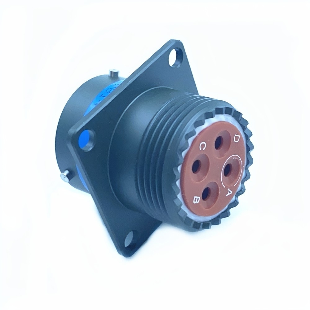
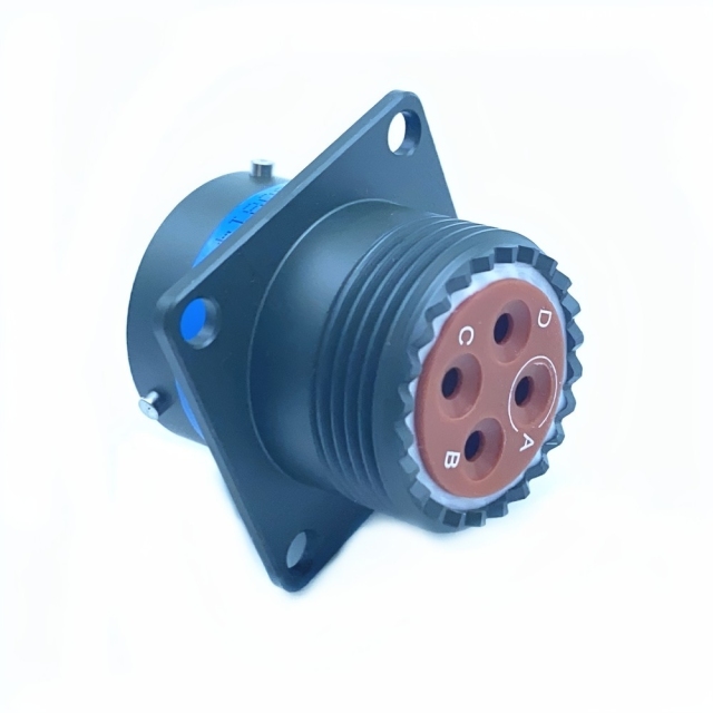
MS3470W14-4SW is a MIL-DTL-26482 connector built as a flange-mount receptacle: a circular metal shell, a square flange with fixing holes that bolts the body flat to a panel or enclosure wall, a keyed insert carrying four labeled contact positions (A to D), and a bayonet coupling ring that locks the two halves with a short twist. Nothing about it is decorative. Every feature exists so the part can be terminated once and then mated and unmated many times without the connection drifting.
It is one of the smaller formats in the Series II family, and that is why it appears so often on weight- and space-limited platforms. An aerospace circular connector of this size disappears into a bulkhead: a UAV airframe, a cockpit instrument panel, a portable communications set, a ground support trolley. The cable bundle runs to the receptacle behind the panel, and the plug side is what crews actually handle in the field.
This half carries socket contacts, so it mates with a plug from the same series; two receptacles do not pair. Because the shell is keyed, the mating plug can only enter the one way it was designed to, and each position is marked inside the insert, so a technician wiring a cable bundle can see the arrangement without counting back from a drawing.
Distributors and cable-assembly shops that carry aerospace and industrial circular connectors on the same line card can treat this military circular connector as one more repeatable reference: it is ordered, kitted and stocked the same way every time, and its mating plug and backshells come from the same family rather than from three different sources.
MIL-DTL-26482 Series II Standard
- What the specification fixes — MIL-DTL-26482 defines bayonet-coupled circular connectors for harsh service: shell sizes and insert arrangements, contact retention, keying, coupling force, and the environmental test regime covering shock, vibration, moisture and temperature extremes. A receptacle and a plug built to the same shell size, insert arrangement and keying are designed to work as one mated pair.
- Why engineers quote it by name — When a drawing, a maintenance manual or a legacy platform calls for a MIL-DTL part, the reference is the requirement rather than a preference. Building to the standard keeps the interface stable across builds and lets a replacement be ordered years later without reworking the loom.
- Where it sits among military circular connector families — the 26482 shell is deliberately small and light and closes with a quarter-turn bayonet action. The larger 38999 families trade some of that compactness for higher contact density. Where panel space and weight are the binding constraints, 26482 is usually the simpler answer.
- Series II in this design — the receptacle is the half that stays bolted to the equipment, while the plug carries the free cable assembly. That split is what lets a panel be assembled and tested on the bench before it ever goes near the platform.
- Common ground between suppliers — because the mating interface is fixed by the specification, parts from different production batches and from different circular connector manufacturers are built to the same interface once shell size, insert arrangement, keying and contact gender agree. It is what makes a mixed inventory workable for a distributor holding more than one brand.
- What the standard does not settle for you — shell material, finish, ingress protection and temperature rating still vary by variant and by order. Those are the four lines to pin down against your drawing before a line item is released.
Materials, Plating & Shielding
Shells in this family are produced in aluminum alloy or in nickel-cadmium plated steel — both light, both machinable, both able to take a plating that survives years of handling. The metal body does two jobs at once: it shields the insert from impact, and it wraps the contacts in a continuous conductive envelope that carries EMI and RFI away from signal lines running beside motors, radar or radio gear. On a crowded panel, that shielding matters as much as the current rating.
Contacts are machined and plated, typically gold over nickel, which keeps contact resistance low through repeated mating and stops the surfaces oxidising in humid air. Plating practice differs between circular connector manufacturers — underplate, gold thickness and shell finish can all vary while the mating interface stays identical — so if your drawing names a finish, send it with the enquiry and we will match against it rather than assume.
Sealing comes from two places: an O-ring or gasket face where the two shells meet, and a grommet at the rear where the wires enter the insert. Both are serviceable items and both are the first thing to inspect if a connector has been sitting unmated on a shelf. Backshells are available in straight and elbow forms, which is how cable routing and strain relief are handled once the flange is bolted down.
Before a production order, confirm the three lines most purchase specifications check first: shell material, shell finish and contact plating. Two connectors can look identical on a bench and still fail a drawing check on the plating callout.
Environmental Resistance
- Vibration — The bayonet lock, the keyed shell and contact retention inside the insert work together to stop the mated pair creeping apart under continuous movement. On airframe panels, engine-adjacent brackets and vehicle hulls, that is the difference between a connection that holds and one that frets itself loose.
- Shock — Landing loads, hard road surfaces and dropped equipment send short, high-energy pulses through a cable assembly. A metal shell and a locked coupling absorb them, and the insert keeps each contact in its own cavity instead of letting the row shift.
- Salt spray — Plated shells are what let mil spec circular connectors survive coastal air, deck spray and de-icing chemistry. Buyers rarely ask for salt-spray resistance for its own sake; they ask because the equipment sits near salt water, gets washed down, or waits months in a humid store.
- High temperature — Enclosed panels, engine bays and equipment left in the sun push inserts and seals well above ambient. The family is built for a broad operating range; ask us for the rated figure for the variant and configuration you are ordering.
- Water and dust — Sealing is what turns the same shell into a waterproof military connector rather than a splash-resistant one. The O-ring at the interface and the grommet at the rear entry do the work, and both stay effective only while they are clean and undamaged.
- Repeated handling — A quarter-turn bayonet is meant to be operated often. The machined coupling ring and the contact plating are what keep the lock feeling positive after a long service life of mating and unmating.
Mounting & Mating Sequence
- Check the panel first: flange footprint, fixing-hole spacing, and the clearance behind the panel for the mated plug and the bend radius of its cable. A receptacle that fits the hole but crowds the cable bundle costs more later than a different shell size would have.
- Match keying and insert arrangement to the plug you intend to use. Shell size, contact positions and key position all have to line up; two parts from the same series still will not mate if the keyways are cut differently.
- Terminate the socket contacts onto the cable bundle, push each one home until it seats, then pull gently back on every wire to prove the retention clip has caught.
- Bolt the flange down evenly, working around the fixing holes instead of tightening one corner first, so the shell sits square against its gasket or sealing face; a waterproof military connector only seals while that face is flat and evenly loaded.
- Mate the plug by aligning the keyway, pushing straight, then turning the coupling ring through its quarter turn until the bayonet seats. Bringing a military circular connector in at an angle is the usual cause of bent contacts and rolled seals.
- Confirm the coupling is fully home before power is applied — check it visually and by feel — then make sure the rear grommet is sitting flat around the cable bundle.
Critical Applications & Reliability
- Aircraft and avionics — flight-control runs, engine monitoring, navigation and communication suites in fixed-wing and rotary aircraft. The receptacle goes on the panel side, so the airframe loom is terminated once and the plug is what gets disturbed during inspection.
- Unmanned systems — UAV and UUV data links and power feeds, where every gram is budgeted and the connector has to survive launch, vibration and recovery. An aerospace circular connector this small fits airframes where a larger shell simply will not.
- Ground vehicles — armored vehicles, personnel carriers and battlefield communication fits, where harnesses take shock, dust and rough handling between deployments.
- Naval and shipboard — communication, radar and weapons-control runs, where a waterproof military connector with a plated shell earns its keep against salt-laden air. For deck-level duty, check the finish called out on your drawing.
- Test and measurement — ground support equipment, test benches and rigs where the same connector is mated and unmated all day. That is where the bayonet action and the contact plating pay for themselves.
- Space and satellite systems — where the programme qualifies it, this format appears on satellite and launch-vehicle harnesses, chosen for low weight and stable contacts under launch vibration, subject to the specific space-grade qualification the programme applies.
- Industrial equipment — industrial circular connectors of this pattern also turn up on machine tools, robotics and renewable-energy cabinets where a sealed metal interface is preferred to a plastic one.
Specifications
| Property |
Value |
| Series |
MIL-DTL-26482 Series II |
| Connector type |
Flange-mount receptacle |
| Coupling |
Bayonet, keyed |
| Contact positions |
4, labeled A to D |
| Contact style |
Socket |
| Shell form |
Circular shell with mounting flange |
| Shell material |
Aluminum alloy or nickel-cadmium plated steel |
| Contact plating |
Gold over nickel |
| Sealing |
Interface O-ring, rear grommet |
| Backshell options |
Straight or elbow |
| Environmental resistance |
Vibration, salt spray, high temperature, water, shock |
| Mounting |
Panel or bulkhead, flange fixing |
Ordering & Export Service
- Quote reference — send the full model number and, if you are replacing an existing part, the number stamped on the old shell or the drawing reference. Where shell size, insert arrangement or keying could be read more than one way, we will confirm before quoting rather than after.
- Quantities — we keep MOQs flexible across the range, so a single spare and a production batch can both be quoted. Confirm the minimum that applies to your specific line item with your sales contact.
- Stock and lead time — availability varies by item and by configuration. Confirm current stock and lead time at the enquiry stage, especially when the date is driven by a build schedule.
- Pricing — quoted per order against the quantity and configuration you need. Volume pricing is confirmed by your sales contact once the quantity is known.
- Sourcing — we buy across the range from established circular connector manufacturers, so a repeat order lands on the same reference and the same finish as the first delivery.
- Packing — connectors are packed to protect contacts, plating and sealing faces in transit. If your warehouse needs a specific pack format, labelling or carton marking, tell us when you order.
- Payment — terms are agreed per order; confirm them with your sales contact when the order is placed.
- Shipping — One-stop export service: we handle the export paperwork that travels with your shipment, so the connector arrives with the documents your customs broker expects.
- Mixed families — if your line card or project covers industrial circular connectors alongside aerospace parts, we can consolidate the requirement into one shipment and one set of documents.
Technical Support & Model Matching
Specifying the right part is easier with an engineer on the other end of the conversation. Our technical team helps you match a requirement to the correct reference — comparing series, contact count, coupling and mounting style against the drawing or part number you already hold — and works through troubleshooting with you when a mated pair or an installed assembly does not behave as expected. We also advise on installation and commissioning practice, and coordinate sourcing, pre-shipment inspection and export documents through our supplier network, so what arrives matches what was agreed.
FAQ
Q1. Is this a plug or a receptacle?
It is a flange-mount receptacle with socket contacts. The flange bolts to a panel or enclosure wall and this side stays behind it; the plug, which carries the free cable assembly, comes from the same Series II family. Two receptacles will not mate with each other, so the plug reference matters as much as this one does.
Q2. Will this MIL-DTL-26482 connector mate with the plug I already use?
Only if four things agree: shell size, insert arrangement, key position and contact gender. Send the number stamped on your existing plug, or the drawing, and we will check it against this receptacle before you order. A plug and receptacle that share a series but not a keyway is the mismatch we are asked about most often.
Q3. How much room does the flange mount need?
The flange sits flat against the panel, so the two figures that matter are the fixing-hole spacing on the flange and the clearance behind the panel for the mated plug and its cable bend radius. Send the panel drawing or a photo of the cutout and we will confirm the fit — a connector that suits the hole but crowds the wiring only shows up as a problem at assembly.
Q4. What temperature range does it work over?
The Series II specification calls for a broad operating range so the connector can sit in an enclosed panel, near an engine or in direct sun without the insert or the seals degrading. The exact figure depends on the variant, the shell finish and the contact arrangement, so tell us the temperature your installation actually sees and we will confirm the rated range for that configuration — that is the number to put into your qualification paperwork.
Q5. Which backshell should I order?
Straight backshells suit cable that leaves the panel square-on; elbow backshells suit tight enclosures where the cable has to turn immediately. Either way the backshell provides the strain relief, so match it to the cable diameter and the route rather than to the connector alone. Tell us the cable type and how much space sits behind the panel and we will point you to the right one.
Q6. How should the connector be looked after between deployments?
Keep an unmated receptacle covered, inspect the interface O-ring and the rear grommet at every unmating, and wipe the shell with a clean dry cloth rather than solvent. If a seal looks flattened or nicked, replace it before the next mating — most sealing failures on this type begin with a damaged grommet rather than with the shell. Check contacts for straightness and seating whenever a cable assembly is reworked.
Q7. Can it be used on spacecraft?
Where a programme qualifies it, this aerospace circular connector format appears on satellite and launch-vehicle harnesses, chosen for low weight, stable contacts under launch vibration, and a metal shell that behaves predictably in vacuum. Space use is subject to the specific space-grade qualification your programme applies, so tell us the requirement and we will confirm what documentation can be supplied.