Product Overview
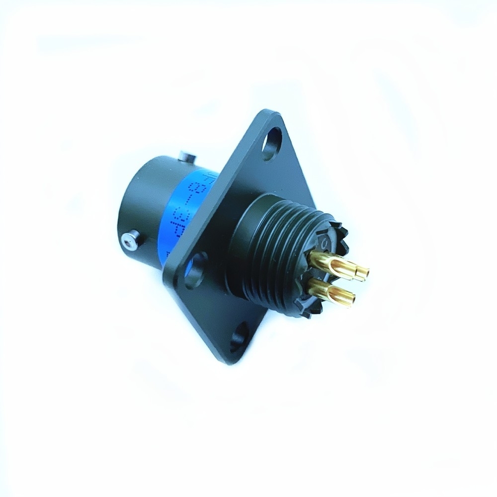
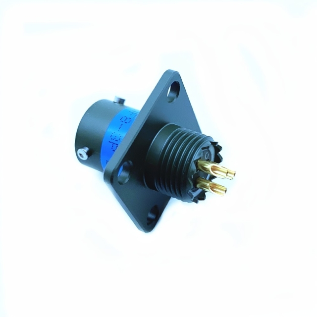
MS3110F08-3P is a sealed MIL-DTL-26482 circular connector from the MIL-DTL-26482 Series I family, supplied as the fixed half of a bayonet-coupled pair. It is a wall-mounting square-flange receptacle in the 08 shell, fitted with pin contacts and the F-type grommet seal with cable clamp. The flange screws flat to the enclosure wall, the wires terminate on the rear body inside the box, and the mating plug comes in from the cable side.
Series I is the bayonet-coupled branch of the 26482 standard, which makes this a bayonet military circular connector in the strict sense: a quarter-turn to lock, a keyed shell that mates only one way, and a sealed contact chamber behind the interface. On a shell this small the bayonet action is a genuine advantage — there is very little room to swing a coupling ring, and a push-and-twist can be done with gloved fingers inside a tight cabinet.
It is a panel mount circular connector at heart, and as a military circular connector supplier we judge one on three details: the flange carries the mounting load, the grommet seal keeps moisture out of the contact chamber, and the cable clamp takes the strain off the termination joints so the loom is not hanging on the contacts. That combination is what makes a connector this small usable on an outdoor cabinet wall, a vehicle hull or the end of a field sensor run.
Electrical Performance
- Gold plating on every contact. The plating is what holds contact resistance low and stable through the service life, and it resists the resistive film that forms on bare copper alloys in humid, salty air.
- Machined contact bodies. Machined contacts keep their alignment over repeated mating; a contact that drifts will start wiping the mating socket at an angle and wear a flat on the pin.
- Headroom for control circuits. The per-contact current and voltage ratings in the specification table cover control, instrumentation, low-power actuation and signal runs. This is not a power connector — for heavy current, take a larger shell or a different family.
- Pin half of the pair. The P in the part number means pin contacts. The pin is the more exposed side of the contact pair, which is why the sealed shroud and the keyed entry matter here: the contacts stay protected until the halves are properly aligned.
- Stable at low signal levels. Dry-circuit and millivolt-level signals are where contact resistance shows up first. Gold plating keeps a low-level signal from being swamped by a film that would be irrelevant at mains current.
- Fixed contact spacing. The insert holds each contact at a set pitch and carries the insertion load, so the pin pattern stays true after repeated mating instead of splaying.
- Worth checking before you specify. Confirm the circuit's actual current and voltage against the ratings, and confirm whether the mating half carries pins or sockets, before the drawing is released — both are points a MIL-DTL-26482 connector manufacturer will settle with you at specification stage rather than at the panel.
Mechanical Durability & Finish
Cadmium sacrifices itself before the base metal, so corrosion shows up as a dulling of the surface rather than as pitting through the shell wall. The flange face and the coupling tracks are where it matters most: those are the two surfaces where a corroded profile stops sealing or stops locking. Coupling is bayonet, and that is the part of the design most people mean when they ask for a bayonet military circular connector. The ring cams over three pins and pulls the halves together with the same preload every time, so mating does not depend on how hard someone turns it. The keyed shell means the halves physically cannot go on in the wrong orientation, and most field damage on connectors this size comes from forced mating or a crossed keyway rather than from electrical wear. Where two connectors on the same panel share a keyway it is a drawing problem rather than a field one, and moving one of them to a different orientation code is the fix — the sort of change a custom military connector OEM makes to the shell without touching the insert. Inside, the insert is a chemical-resistant thermoplastic that fixes each contact at its pitch and takes the insertion load off the retention clips. That is what keeps the pin pattern aligned over a long service life; once an insert moves, the pins splay and the mating half starts to feel tight before it seats. Mating life is stated in the specification table. Two practical points sit alongside it: the cable clamp absorbs loom movement so the terminations never carry it, and the plated contact surfaces resist the fretting that vibration produces as the halves move a few microns against each other.
Compliance & Certification
The connector is built to MIL-DTL-26482 Series I, Revision G, and every unit goes through environmental sealing and high-vibration checks before it ships. Manufacturing runs in an ISO 9001:2015 certified facility, and RoHS/REACH-compliant versions are available where a program requires them. As a custom military connector OEM we also build to a customer drawing where no catalogue arrangement fits — a different insert, a different finish code, a contact gender change — and we will say so plainly when a drawing needs a change rather than a different connector. Agree the documentation with us at the quotation stage: the inspection record for the lot, the finish and plating called out on the drawing, and the compliance statement your incoming inspection works to. Tell us what will actually be checked at goods-in and we will confirm what travels with the shipment. The value here is not a single number on the sheet; it is what stays constant across a fleet. That backward compatibility is the cheapest reliability measure available to a sustainment program. The second layer is lifecycle cost. A sealed, plated interface that holds its preload through vibration and thermal cycling pushes out the replacement interval, and every interval pushed out is a depot visit that does not happen and a platform that stays available. When a program asks us to act as a custom military connector OEM, it usually starts with one part that keeps failing; the answer is more often a correctly matched shell, insert and finish than a different connector. The third layer is logistics. A standard interface interoperates with the tooling, contact kits and mating hardware the program already owns, so there is nothing new to qualify at the bench. That is an unglamorous benefit, but it is the one that shows up when a build is under schedule pressure.
Compact Shell & Panel Fit
- The smallest shell in the range. A small shell buys panel space. On a crowded cabinet wall it lets you place a sealed interface between a relay, a terminal block and the next cutout without moving any of them.
- Three contacts for one dedicated run. A three-contact layout suits a short, defined circuit — an actuator supply, a sensor pair, a single signal group. If the run carries many more conductors, move up a shell size rather than splitting it across three small connectors.
- Square flange, four fixing points. The flange pulls down evenly on all four corners, so the sealing face stays square to the cutout instead of cocking on one edge and letting water in at the opposite side.
- Shallow behind the panel. The rear body and cable clamp sit close to the wall, which keeps the connector clear of DIN rail and terminal blocks inside a shallow box.
- Sized for drop leads, not main looms. The realistic jobs are a drop from a junction box to a field device, a tail on a pressure or flow sensor, or a short link between two enclosures — runs where a larger shell would be overkill and awkward to dress.
- When to step up. If the cable jacket falls outside the clamp range, or the circuit needs more than the insert accepts, go up a shell rather than forcing the gland. A clamp that does not grip properly is the most common cause of a seal that fails in service.
- Matching the other half. This receptacle is only half a coupling; the plug has to come from the same shell size, insert arrangement and keyway. Send the part number on the existing plug and we will confirm the pair — as a military circular connector supplier we handle both halves, not just the receptacle.
- Coupling style. The shell is bayonet. If your drawing calls for a threaded coupling military connector, check before you order: the two interfaces do not interchange and the mating half has to match.
Installation & Mating
- Cut and drill for the flange. Work from the flange drawing, not from the connector body. On a panel mount circular connector the four fixing holes and the contact chamber opening have to line up together; a cutout that is off-center loads one side of the flange and distorts the sealing face.
- Terminate before mounting. Fit the contacts, then the grommet, then the cable clamp, in that order. Once the flange is screwed down there is very little room behind the wall to redo a termination.
- Check the keyway before you push. Line the key up with its slot in the mating shell, then push and turn a quarter-turn until the coupling ring clicks over its pins. If it needs force, the key is not engaged — stop and look.
- Mate by the coupling ring only. Turn the ring, never the body or the cable. Turning the body twists the loom inside the box and works the terminations loose behind the panel.
- Confirm which coupling you have. If the mating item on the bench is a threaded coupling military connector rather than a bayonet shell, it will not fit however carefully it is offered up. Check the interface style before the job starts.
- Seat the halves fully before testing. A bayonet shell that is only part-turned can read continuity on a meter and still let water past the interfacial seal. Lock it, then test.
- Leave a service loop. Give the cable a small loop inside the enclosure so the clamp, not the termination, takes any pull on the loom.
- Wipe the seal faces on reassembly. A grain of grit or a nicked grommet on the sealing face is enough to break the rating. Clean the interface before the halves go back together.
- The Jam-n keyed coupling prevents mis-mating and ensures polarized connections. EMI/RFI shielding effectiveness meets MIL-STD-461 requirements.
Target Applications
- Aerospace avionics and flight-control bays. Vibration, pressure cycling and wide temperature swings are the normal working conditions here; a sealed small-shell connector keeps a control or indication circuit intact where an unsealed one would need routine attention.
- Ground combat vehicle electronics. Hull-mounted cable assemblies take shock, dust and wash-down. This MIL-DTL-26482 circular connector suits the short runs between a distribution box and a subsystem rather than the main cable trunk.
- Naval shipboard and deck equipment. Salt-laden air and regular hosing are the two conditions that finish off unplated connectors; a cadmium-plated shell and a sealed interface are the minimum for anything mounted outside the citadel.
- Undersea sensor arrays and communication buoys. The sealed contact chamber and cable clamp suit a sensor tail that is handled, deployed and recovered rather than permanently potted into a housing.
- Oil, gas, mining and heavy machinery. Control cabinets in these industries routinely need an ip67 military circular connector where the field cable leaves the enclosure — a sealed interface is far easier to live with than a failed sensor run.
- Outdoor instrumentation and test equipment. Field-deployed meters, loggers and test boxes use small sealed receptacles so the case can be closed against rain without a dedicated gland plate.
- Cable assembly build and repair. A single replacement receptacle keeps a cable assembly in service when the original has corroded or been damaged in handling.
Technical Specifications
Sealing is rated IP67. In practice that means a dust-tight contact chamber that survives temporary immersion — a deck wash, a hose-down, a boot full of water — without moisture reaching the contacts. It puts the connector in the outdoor and marine bracket rather than the sheltered-panel bracket, which is the working definition behind an ip67 military circular connector. Three components do the work. The rear grommet grips each wire individually so nothing weeps along the conductor into the shell. The interfacial seal between the mating halves closes the gap the moment the coupling locks. The cable clamp on this F-type shell stops the jacket being pulled back through the grommet when the loom is tugged during installation or service. The grommet is the part most often got wrong. Match the grommet holes to your actual wire gauge: a grommet sized for a thicker wire will not seal on a thin one, and that single mismatch accounts for most wet connectors sent back from the field. If your cable mixes wire sizes, give us the schedule when you order so the right grommet is fitted. Temperature is listed in the specification table and spans the cold soak of a high-altitude ramp as well as radiant heat near an engine or exhaust run. Thermal cycling is the harder of the two conditions: repeated expansion and contraction works on every seal face and plated surface, so the interface has to hold its preload, not merely its shape.
| Parameter | Specification |
|---|
| Shell material | Aluminum alloy |
| Shell finish | Cadmium plated to MIL-STD-171 |
| Shell size | 08 |
| Contact type | Pin contacts |
| Contact plating | Gold over nickel |
| Insert material | Thermoplastic |
| Sealing | IP67 |
| Temperature range | -65 °C to +175 °C |
| Current rating | Up to 5 A per contact |
| Voltage rating | Up to 500 V |
| Mating cycles | 500 minimum |
| Coupling | Bayonet, keyed |
| Mounting | Wall-mounting square flange, grommet seal and cable clamp |
Series I Part-Number Reference
| Position in the code | What it controls |
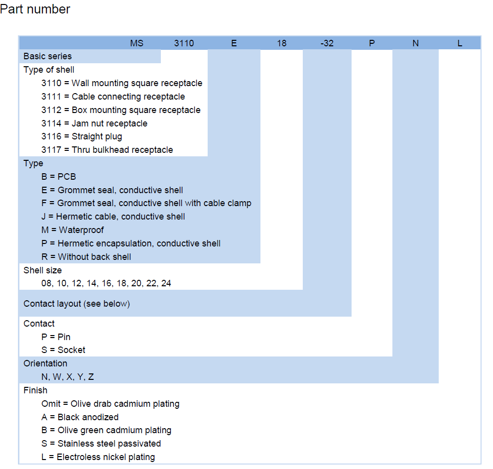
| Basic series | 3110 wall-mounting square receptacle; the range also covers 3111 cable-connecting, 3112 box-mounting, 3114 jam-nut, 3116 straight plug and 3117 through-bulkhead shells |
| Type letter | E grommet seal with conductive shell, F grommet seal with cable clamp, J hermetic cable, M waterproof, P hermetic encapsulation, R without back shell |
| Shell size | 08 through 24 in steps; the size sets the overall diameter and which insert the shell can carry |
| Contact layout | The number after the dash selects the insert arrangement, and with it the number and size of the contacts |
| Contact type | P for pin contacts, S for socket contacts |
| Orientation | N, W, X, Y or Z keyway position, used to keep two adjacent connectors from being cross-mated |
| Finish | Omit for olive-drab cadmium, A black anodized, B olive-green cadmium, S stainless steel passivated, L electroless nickel |
Ordering & Delivery
- Order by part number. The code carries shell size, insert arrangement, contact type, keyway and finish, and that is what gets built and inspected. As a MIL-DTL-26482 connector manufacturer we quote from the code — a photograph is not enough at this shell size, where several variants look identical.
- Supplied direct. We work as a military circular connector supplier from our own production, so the part you order and the part that is manufactured are the same item.
- Flexible MOQs. Order quantities are flexible — a single replacement receptacle and a production release both run down the same line, so a repair does not have to wait for a batch.
- Stable global delivery. Delivery is planned and held stable so a build program is not left waiting on one connector; export shipments go out from Shenzhen.
- Lead time. Ask for the lead time against your quantity and finish code with the quotation; the finish and the contact arrangement both affect scheduling, and we would rather quote a date we can hold.
- Packing. Tell us how the parts need to arrive — individually bagged, kitted with the mating plug, or bulk for a cable assembly bench — and the packing will be agreed with the quotation.
- Payment and shipping terms. Confirm the payment terms and the shipping terms you need for the order with your sales contact; terms are agreed per order.
- First articles and sample requests. If your process needs a first article or a sample before a program commits, say so with the enquiry and we will confirm what can be supplied and on what schedule.
Technical Support & Model Matching
Selecting the right connector is rarely a one-line decision. Send us your drawing, part number or a sample, and our engineering team will confirm the matching shell size, contact arrangement, coupling and mounting style, cross-reference discontinued or alternate part numbers, and advise on sealing and flange options for your environment. We also help troubleshoot fit, mating and signal problems, and give installation and commissioning guidance so your line stays up. As a direct manufacturer, our answers come from the people who build the parts — from first enquiry through after-sales support.
FAQ
Will this receptacle mate with the plug already fitted to our wiring assembly?
It will if the plug matches on shell size, insert arrangement, keyway position and coupling style — in a MIL-DTL-26482 circular connector those four things define the interface, not the part number alone. Send us the marking on the existing plug and we will confirm the match against this receptacle before you order. What we cannot do is make a different insert arrangement fit: the keyway and the contact positions are fixed by the shell.
The contacts are pins — does that mean the receptacle has to be the fixed half?
No. Pin or socket is a contact choice within the shell, and either can be supplied on a receptacle or on a plug. What fixes the arrangement is the shell style, not the contact gender. If your wiring convention puts sockets on the powered side, tell us when you order and we will confirm the matching half.
How long will the coupling stay tight?
Mating life is stated in the specification table, and the bayonet military circular connector coupling holds its preload by cam action rather than by friction, so it does not slacken with repeated use the way a worn thread can. In service the seal and the plating age before the latch does, so a periodic look at the grommet and the keyway covers most of what goes wrong.
Can this be mounted through the wall of a sealed enclosure?
Yes — that is what the square flange is for. The panel mount circular connector screws flat to the wall over the cutout, and the interfacial seal closes against the mating plug from the outside. Two details decide whether it stays sealed: the cutout must match the flange drawing so the flange does not distort, and the grommet at the rear must match your wire gauge. Deburr the cutout before assembly, because a burr under the flange is a leak path.
Our drawing says threaded coupling — is this the same connector?
No. MIL-DTL-26482 Series I is a bayonet interface: push, quarter-turn, lock. A threaded coupling military connector uses a different interface and will not mate with this shell, however similar the two look. If the drawing specifies a threaded coupling, tell us and we will point you to the correct interface rather than supply a part that will not fit. If the drawing says 26482 Series I, this is the right coupling.
Does IP67 mean the connector can stay underwater?
IP67 covers dust-tightness and temporary immersion, not continuous submersion. Rain, wash-down, a swamped compartment or a connector dropped in a bilge are within scope; a permanently submerged housing is not. That distinction is the difference between an ip67 military circular connector and a subsea-rated one, and it is worth being clear about before the enclosure is designed.
Can you build this to our drawing instead of the standard configuration?
Often, yes. Finish code, keyway position, contact gender and shell style are separate choices in the part number, so many custom requests turn out to be a standard build with a different code. Where the request genuinely falls outside the catalogue range, tell us what the drawing needs as a custom military connector OEM enquiry and we will confirm what can be built and what has to change.
We need a compliant build — what happens to the cadmium plating?
Cadmium plating is the standard finish. Where a program needs a RoHS/REACH-compliant build, that is handled through the finish code — black anodized, stainless steel passivated and electroless nickel are the usual starting points. Tell us the compliance statement your program works to at the quotation stage and the finish will be matched to it; if in doubt, specify the finish code on the drawing instead of leaving it to the default.