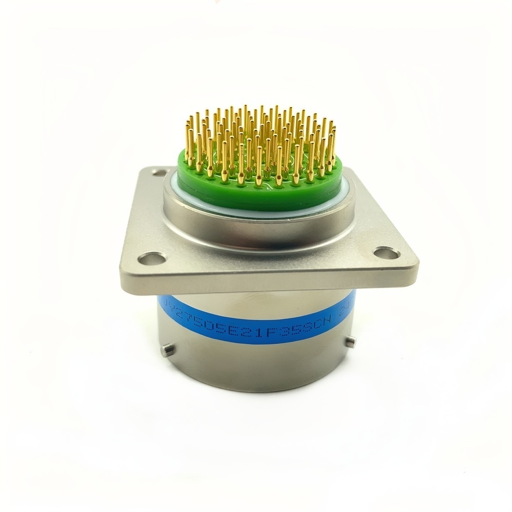
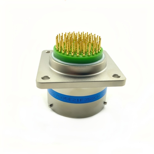
The MS27505E21F35SCN is a MIL-DTL-38999 Series I circular connector with a threaded coupling, supplied in panel mount and cable mount formats. Series I is the original shell style in the 38999 family, and the threaded collar is the detail most drawings rely on: once the halves are mated they stay mated, with no secondary latch to inspect, adjust or lose.
The panel version carries a square flange, with the pin field standing in a green insulator insert and the gold-plated contacts exposed for inspection before the halves are joined. The cable version is built onto a loom. Both are drawn from the same interface, so a fixed bulkhead position and a cable assembly in the same program can share one line on the bill of materials.
Because the interface follows a published specification, this D38999 connector can be checked clause by clause against an existing bill of materials rather than matched by eye — useful when the person placing the order is not the person who originally specified the part.
We supply it to distributors, panel builders, cable assembly shops and project teams running aerospace, defense and industrial equipment. As a supplier of military circular connectors, we keep the reference steady across repeat orders: same model, same coupling, same mount format, order after order.
| Parameter | Value |
|---|---|
| Series | MIL-DTL-38999 Series I |
| Coupling | Threaded |
| Mounting formats | Panel mount and cable mount |
| Termination | Solder cup contacts |
| Operating temperature | -65 °C to +200 °C |
| Contact current rating | 5 A per contact, derated per the temperature curve |
| Shell style | Square flange for panel mounting, cable-end body for cable assembly builds |
Shell. The shell is aluminum alloy, chosen for the balance between weight and thread strength that airborne panels demand. Cadmium plating sits underneath a tin finish: cadmium is the corrosion barrier, and tin gives the outer surface a uniform finish that does not oxidise in store. Programs that restrict cadmium by substance policy should raise it before the order is released, because the finish is applied at shell level and cannot be changed afterwards.
Contacts. Contact bodies are beryllium copper, alloy C17200, a spring-temper material picked because it holds contact force through repeated mating rather than relaxing and letting resistance climb. Each contact carries 50 microinches of gold over 100 microinches of nickel. The nickel acts as a diffusion barrier between the gold and the copper alloy; the gold is what keeps contact resistance low and stable at the small currents a signal circuit draws. On MIL-DTL-38999 connectors handling low-level signals, that stack is the reason readings stay repeatable between services instead of drifting.
Dielectric. The insert is a PTFE-based composite with a relative permittivity around 2. Low permittivity keeps capacitance between neighbouring contacts small, and the PTFE base holds its electrical properties across a wide temperature band while absorbing very little moisture — useful in an enclosure that breathes between hot and cold cycles.
Before release, check the finish callout against your program's substance restrictions and against the sample or first article you have approved.
The threaded coupling is the reason this connector is chosen for frames that move. A quarter-turn bayonet is faster to operate, but a thread turns vibration into a slight rotation of the collar instead of a release, so the halves stay seated with no safety wire to fit. For MIL-DTL-38999 connectors mounted on engine frames, rotor heads or vehicle hulls, that one detail removes a class of intermittent faults otherwise traced back to a connector that looked secure on the bench.
Vibration performance is specified against MIL-STD-202, Method 204 — the swept sinusoidal profile used to qualify components. What the test really answers is whether contact pairs stay in touch as the frequency sweeps, which is the condition a cable assembly actually meets on a running platform rather than during a single handling drop.
Mating durability is rated at 500 cycles minimum without degradation of the electrical parameters. On a panel connector mated once at build, that is a generous figure; it starts to matter on test racks, ground support equipment and anything opened daily. Where cycling is frequent, set the inspection interval around the coupling thread and the contact surfaces rather than around the calendar — thread wear shows first as a collar that turns a little further before it seats.
Three handling habits protect that rating: keep the protective cap on until the cable assembly is ready, pull the halves apart by the shell rather than the cable, and leave a service loop long enough to turn the coupling ring without loading the solder cups.
Avionics is where the Series I format is most often specified — flight control runs, navigation boxes and communication equipment, all fixed to a rack and disturbed only at maintenance. Military ground vehicles use the same shell for ECU interconnects and sensor networks that have to survive shock loads and long spells outdoors. Satellite payload interfaces call for it for a different reason: the connector has to hold its electrical values through launch vibration and then through repeated thermal cycling in vacuum.
In plant environments these industrial circular connectors turn up on robot arms, machine-mounted control boxes, test fixtures and process skids, where the panel half is bolted to a frame and the cable half is cycled far more often than on an aircraft. Medical imaging equipment uses them where a scanner needs a screened, repairable interconnect that will not drift between calibrations, and undersea monitoring installations take the sealed version wherever a pressure boundary is involved.
Ground support equipment and bench cable assemblies are another steady home for MIL-DTL-38999 connectors, because there the joint is opened and closed constantly and the cycle rating is a working number rather than a formality.
If your equipment sits outside that list — a rail cabinet, a mobile generator, a test cell — the same interface usually still fits. The questions to settle first are the mount format and the backshell, because those are what the panel and the cable assembly have to match.
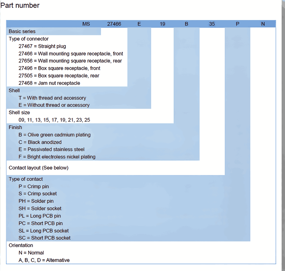
Quotes are built against the model reference MS27505E21F35SCN together with the coupling style, mount format and contact arrangement you need, so the reply matches the line on your drawing rather than a family description. Send the reference, the quantity and the destination, and our team will confirm the minimum quantity and lead time for that line before you release the order.
We supply as a military grade connector supplier to distributors, agents and project buyers, and mixed orders across the 3899 and 26482 families are normal — one shipment can carry several references for the same build. Every order moves under our one-stop export service, so the documents and handover your import side needs are handled with the shipment rather than chased afterwards.
If you need a first article before committing to a build, ask your sales contact about sample availability and the lead time for it. Connectors travel in export packing suited to air freight; if your receiving bay needs particular carton marking or a specific pack configuration, say so on the order so it is set up at packing rather than after dispatch.
Repeat orders are the simplest case: quote the same reference and the D38999 connector is supplied to the same drawing, which is what keeps a multi-year program consistent between builds.
A high-reliability electrical connector is built for the moments when a connection simply cannot fail. This one is engineered for applications where performance, durability and signal integrity are non-negotiable, holding a secure and efficient connection even in the most challenging environments. Inside electronic systems it serves as a critical component, where consistent contact and long service life matter more than anything else. If you need the exact specifications for your design, our team can confirm the details with you before you order.
Specifying the right part is easier with an engineer on the other end of the conversation. Our technical team helps you match a requirement to the correct reference — comparing series, contact count, coupling and mounting style against the drawing or part number you already hold — and works through troubleshooting with you when a mated pair or an installed assembly does not behave as expected. We also advise on installation and commissioning practice, and coordinate sourcing, pre-shipment inspection and export documents through our supplier network, so what arrives matches what was agreed.
It is built for fixed panels and cable runs in aerospace, defense and heavy industrial equipment — avionics racks, vehicle ECUs and sensor networks, satellite payload interfaces, robot arms and imaging systems. Wherever industrial circular connectors have to keep a sealed, screened interface stable through vibration and repeated service access, this format is a fit. Send us the enclosure and the cable layout and we will confirm the mount and backshell.
Yes. This model uses a threaded coupling, and bayonet versions are available in the same range for positions that need faster access. Electrically the two behave alike, so the choice comes down to how often the joint is opened and whether a tool-free quarter-turn is worth more to your operators than a thread that resists loosening on its own. Both styles are supplied as military circular connectors with the same contact and shell principles.
Both. As a military panel mount connector it bolts through a bulkhead or enclosure wall on its square flange; the cable version is built onto a loom and mates into it. Taking the two halves from the same interface keeps the panel aperture, the keying and the backshell thread consistent across the whole build.
EMI filter backshells to M85049 fit the shell directly, with no adapter in between. Choose the backshell for your cable diameter and the screening you need, and order it with the connector so the thread and the gasket are matched at the same time. If your cable assembly already carries a backshell reference, send it with the enquiry and we will confirm compatibility.
Yes. The contacts are solder cups, so a single joint can be opened, cleaned and re-made at the bench while the rest of the connector stays in place. Keep the heat local and support the wire while the joint cools — an over-heated cup softens the insert around it, and that is the most common way a repairable connector stops being repairable.