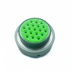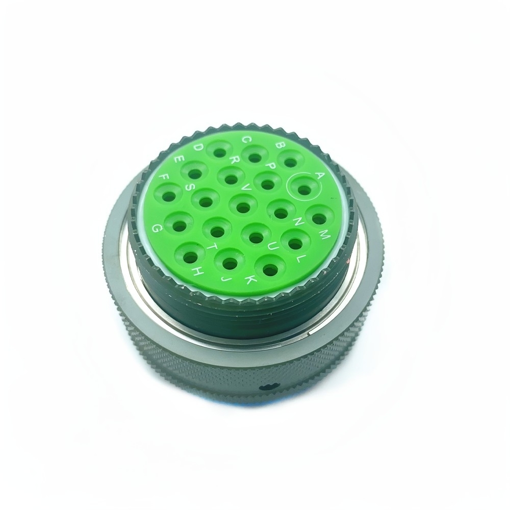
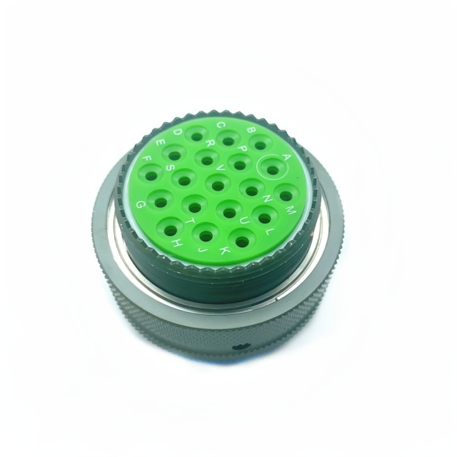
This is a MIL-DTL-38999 Series I circular connector in plug-and-socket form, sized for the panels, cable assemblies and equipment bays where the surrounding hardware has to keep working while the platform vibrates, heats up, cools down and gets wet. The machined shell carries the coupling ring, the insert locks the contacts into a fixed pattern, and the whole assembly is plated and sealed so the electrical interface stays stable when the conditions outside it are not.
Buyers arrive at this part from two directions. Some are building new equipment and need the interface to match a drawing exactly; others are replacing a unit already in the field and need the number on the old shell to match the new one. Both come down to four checks — shell size, contact arrangement, contact gender and keying — because if those disagree, nothing else about the part matters.
In service it sits between subsystems: a control module and its cable assembly, a sensor run and the box it feeds, a power distribution point and the equipment downstream of it. It is not a consumer part and is not intended for household wiring or low-cost commercial equipment; it exists for installations where an intermittent contact takes a system offline and sends a technician back to the same panel.
The reference sits among the MIL-DTL-38999 connectors we supply for aerospace, defense and rugged industrial builds, and it is ordered most often against a BOM line or a failed unit rather than as a first-time design choice. If you are working from a drawing, start there. If you are working from a fielded unit, start with the number stamped on the shell.
| Series | MIL-DTL-38999 Series I |
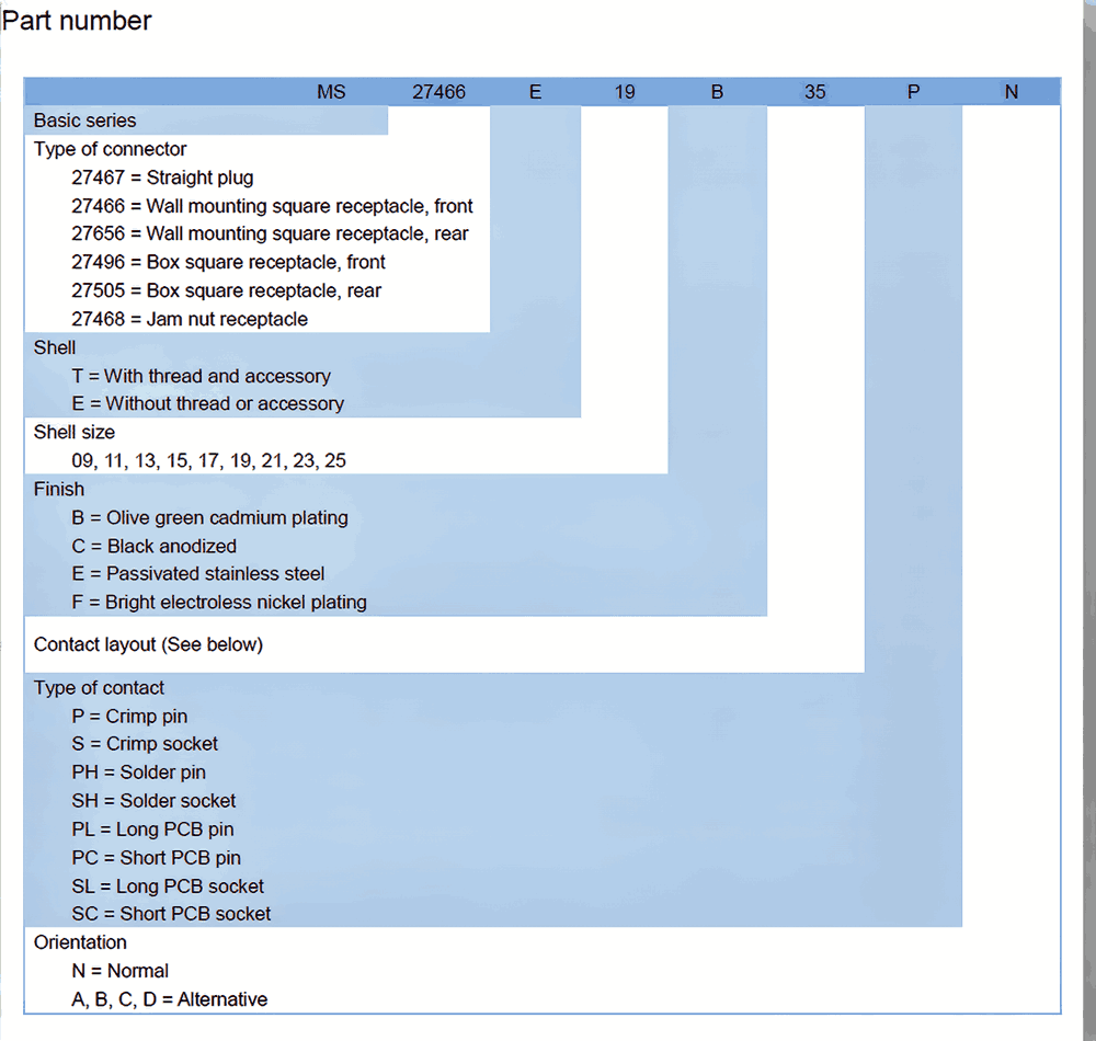
| Part number | MS27467T25B19PN |
| Contact termination | Solder cup |
| Operating temperature | -65 °C to +200 °C |
| Current rating | 5 A per contact, derated per the temperature curve |
| Vibration | MIL-STD-202 Method 204 |
| Mating durability | 500 cycles minimum |
| Pressure integrity | Tested to 15 psi differential |
| Sealing | IP68 when mated with a suitable backshell |
Shell. The housing is an aluminum alloy, chosen for strength at low weight, plated with cadmium and finished in tin. The cadmium layer is the corrosion barrier: where a scratch or a tightening mark cuts the finish, it keeps working on the exposed metal underneath. The tin on top gives a uniform, conductive outer surface and a finish that still looks like a connector after months in a stores bin.
Insert and dielectric. The contact cavities sit in a PTFE-based composite. PTFE holds its electrical properties across a wide temperature span, takes up very little moisture and does not soften the way cheaper thermoplastics do, so the insert does not shift the contacts when the assembly goes through thermal cycling.
Contacts. Contacts are machined from beryllium copper (C17200), a spring-temper alloy that keeps its contact force instead of relaxing over time, and plated with 50 microinch of gold over 100 microinch of nickel. The nickel is a diffusion barrier between the gold and the copper alloy; the gold gives the low, stable contact resistance that repeated mating does not erode.
Sealing path. Conductive elastomer gaskets sit at the interface, at the shell joint and at the cable entry, so moisture has three separate seals to get past before it reaches a contact. The rear seal only becomes complete once the right backshell is fitted, which is why a bare connector and a finished assembly should never be described the same way.
Mechanical detail. The shell is keyed so the two halves can only go together one way, and the coupling ring is knurled so it can be turned by hand with a glove on. A technician can feel the ring come up against its stop, which is a more reliable check in a dark equipment bay than looking at it.
The plating and contact schedules behind this reference come from the MIL-DTL-38999 manufacturer data for the part rather than from a substitution made to hit a price, which is what keeps the corrosion behaviour and the contact resistance consistent from one lot to the next.
Aircraft systems and flight control. Flight control, navigation and communication runs pass through connectors that see pressurisation cycles, engine heat and constant airframe vibration. This part is used where an avionics box meets its cable assembly, and a contact that opens in flight cannot be fixed with a reset.
Military ground vehicles. Engine control units, sensor networks and communications kit in wheeled and tracked vehicles live with dust, water crossings, shock loads and long periods of standing. A sealed circular interface keeps the cable-assembly side serviceable when the electronics are swapped.
Satellite payload interfaces. Payload and bus interfaces are mated at integration and then have to hold through launch loads and thermal vacuum. The shell and insert arrangement is chosen so the interface survives the handling between bench test and final mate.
Industrial robotics and automation. High-vibration cells, welding lines and machine tools use this class of connector where a commercial part would fret loose. The locking ring and the retained contacts matter more here than the military pedigree.
Medical imaging equipment. MRI and CT interconnect runs need stable contact resistance and an interface that does not corrode when the enclosure is cleaned regularly.
Undersea and coastal monitoring. Pressure housings, dock equipment and shore stations put salt and permanent damp against the shell. This is where the plating earns its place.
Test benches, ground support and rugged control panels. Bench cable assemblies are plugged and unplugged far more often than flight hardware, so mating life matters as much as sealing.
Taken together, these are the working conditions the MIL-DTL-38999 connectors in this size class are specified for, and the reason the part is usually written into a drawing rather than picked off a shelf.
Specifying the right part is easier with an engineer on the other end of the conversation. Our technical team helps you match a requirement to the correct reference — comparing series, contact count, coupling and mounting style against the drawing or part number you already hold — and works through troubleshooting with you when a mated pair or an installed assembly does not behave as expected. We also advise on installation and commissioning practice, and coordinate sourcing, pre-shipment inspection and export documents through our supplier network, so what arrives matches what was agreed.
It is a MIL-DTL-38999 Series I circular connector for aerospace and defense wiring — the interface between a wire bundle and an equipment box, or between two subsystems that have to stay connected while the platform vibrates, heats and cools, and gets wet. It carries signal and power across a plated, sealed shell, and it is ordered against a drawing or a part number rather than picked for appearance. We supply it through our mil-spec connector manufacturer network to distributors, system integrators and maintenance teams who need the reference to be right the first time.
Yes — vibration, shock, salt spray, high temperature and water exposure are the conditions it is specified for. The plated aluminum shell carries the corrosion load, the PTFE-based insert keeps the contacts where they belong through thermal cycling, and the beryllium copper contacts hold their spring force instead of relaxing. The one point to keep in mind is that the rear of the connector is only as sealed as the backshell fitted to it, so the water rating belongs to the finished assembly as much as to the bare shell. Our MIL-DTL-38999 manufacturer partners build and test each unit to the drawing before it is packed.
A single circular connector — shell, insert, contacts and coupling ring — supplied as one unit, not as a mated pair unless you order the mating half as well. The reference on the shell identifies the series, the shell size, the contact arrangement and the contact gender, and those four elements are what you compare when you check a quotation. If you are weighing our MIL-DTL-38999 connectors against another source, compare those four before you compare anything else.
Yes. It is built for aircraft systems, ground vehicles, satellite payloads, field equipment and the other assemblies served by the military circular connectors we supply. What decides success in those programs is the integration around the connector: the panel cut-out, the mating receptacle, the backshell, and the way the cable bundle is supported so the shell never carries cable weight.
Confirm the mating interface and shell size, the contact arrangement and contact gender against your drawing, the keying so a similar connector cannot be mated by mistake, and the backshell thread if you need a sealed or filtered rear. Then check the electrical side: the current per contact against your load and the temperature curve, and the voltage rating at your operating altitude. As with any of the mil spec circular connectors in this class, the fit check is the step that decides whether the assembly works — send us the drawing or the number from the old shell and we will check the reference before the order ships.
Household wiring, consumer electronics and low-cost commercial equipment, where there is no shock, moisture or specification requirement and a general-purpose connector will do the job for less. It is also the wrong choice where the design calls for a modified shell, a non-standard contact layout or a custom rear interface: the parts we supply are standard references within the military circular connectors range, so a modified drawing needs to be discussed before an order is placed.
The front of the insert carries lettered contact positions — A, B, C and onward, with I and O left out — so every contact has an address rather than a hole number. When you are building a wiring assembly or tracing a fault, you work from the letter on the drawing to the letter on the insert instead of counting round the circle. On these mil spec circular connectors the lettering also gives a fast check after rework: a contact sitting in the wrong position is visible before the unit goes back into service.