Product Overview
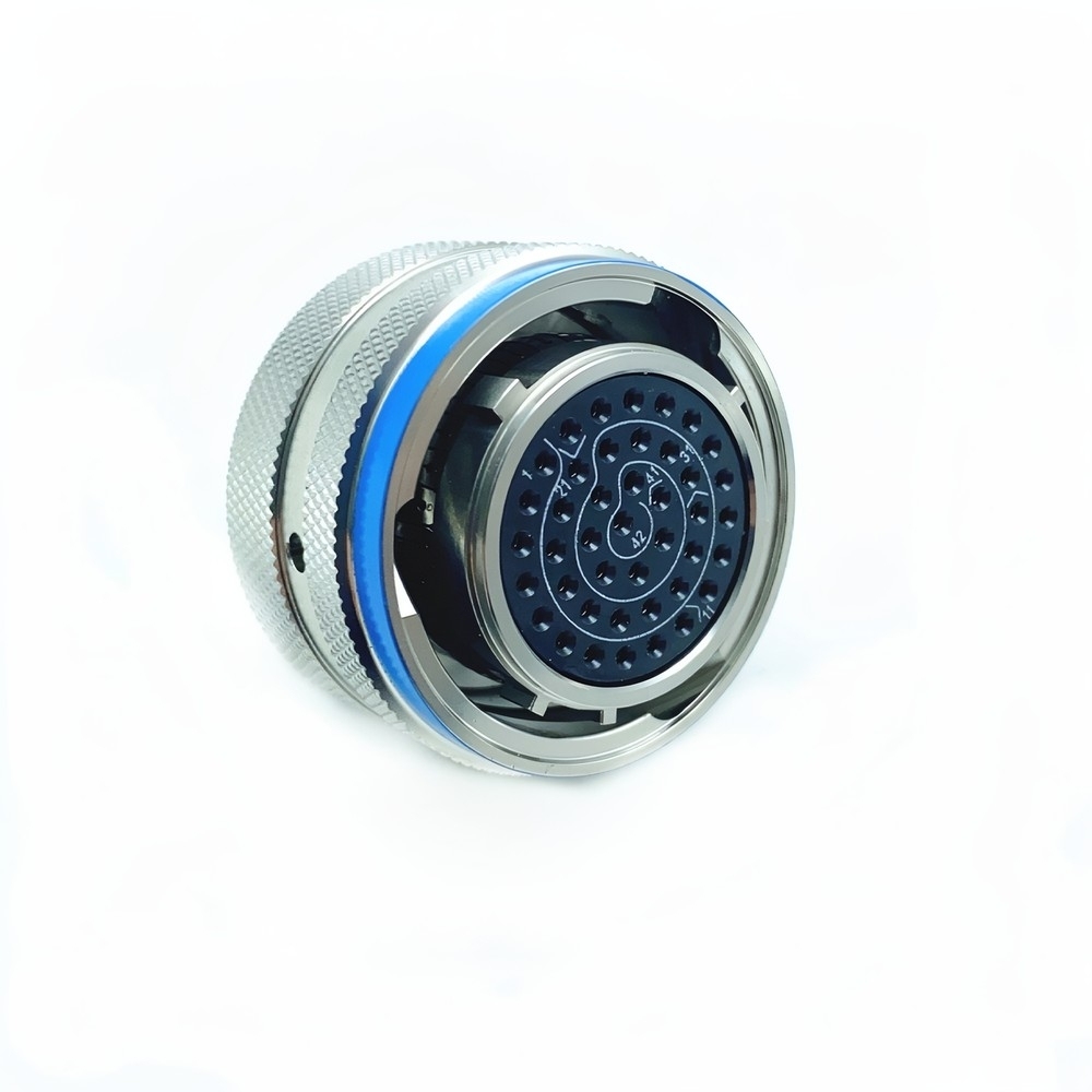
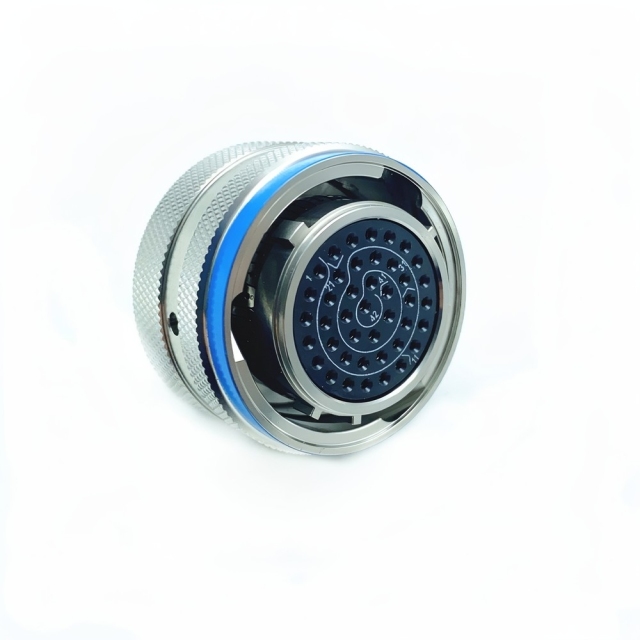
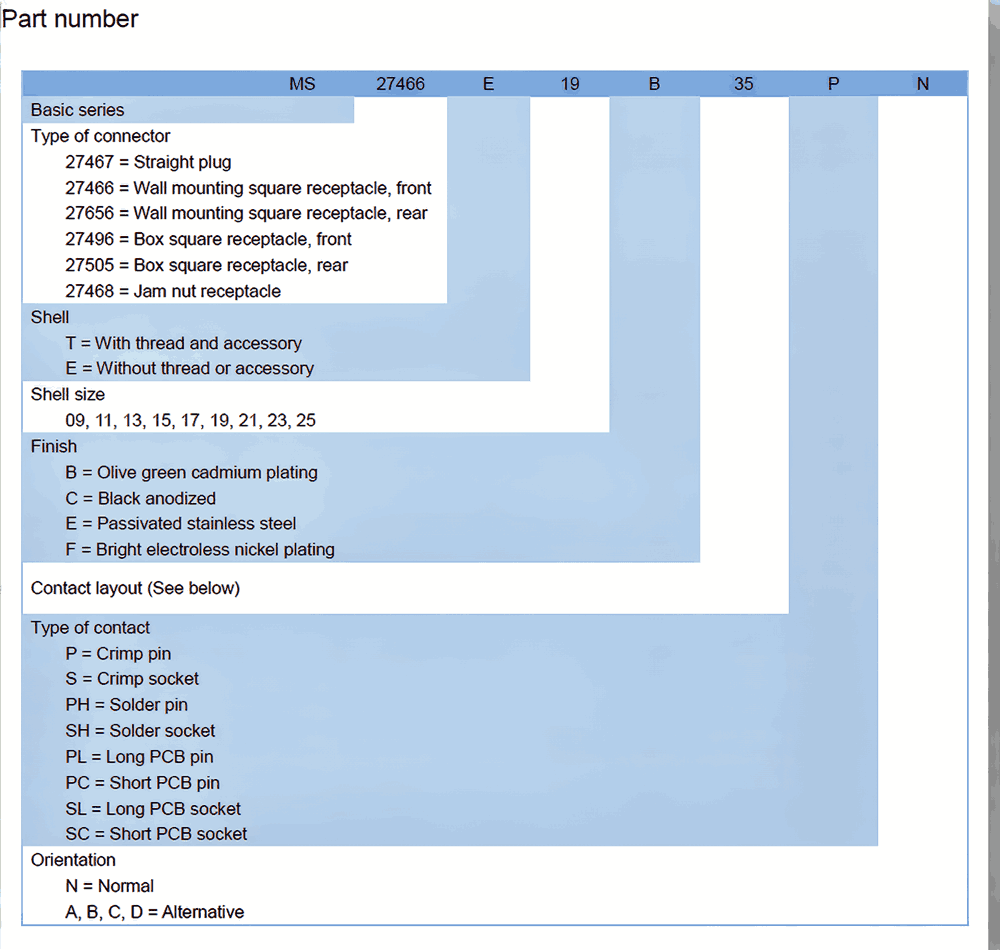
This is a MIL-DTL-38999 connector from the Series I range — MS27467T17E42SN — built for the wiring behind flight controls, ground vehicles and field equipment, where an interface has to stay mated through vibration and still come apart cleanly when a technician needs it to. The shell is round and compact, so it takes a single circular panel opening instead of the wide footprint a rectangular connector needs, and the contacts sit in a numbered insert that tells a wireman which cavity is which before the first conductor goes in.
Coupling is threaded. The ring turns onto the mating shell and stays there, which is what keeps the interface closed when everything around it is shaking. Panel-mount versions fix to an enclosure wall; cable-mount versions sit on the cable assembly end. Both come from the same family, so an assembly can use a fixed receptacle on the box and a plug on the cable without pulling a second military circular connector range into the bill of materials.
Termination is solder cup, which suits cable assembly shops working short runs and repairs: strip, tin and solder each conductor into its own cup, then inspect the joint before the shell goes together. No contact-specific crimp tool is needed at the bench.
In service it behaves like hardware rather than a consumable. Cable assembly builders fit it once; maintenance teams then mate and de-mate it during inspections, upgrades and line replacements, and the keying stops a wrong-socket connection. Distributors hold it as a program-support item, OEMs fit it as a production component, and MRO teams use it as a direct replacement for the same reference already on the aircraft or vehicle.
Key Advantages
- A round shell that fits where a rectangle will not — one circular panel opening instead of a wide cut-out, which leaves room for neighbouring connectors, cable bundles and service access on a crowded bulkhead.
- Panel version for the box, plug version for the cable — the same interface serves a fixed receptacle on an enclosure wall and a plug on a cable run, so both ends of an assembly stay inside one family.
- Threaded coupling that stays put — the coupling ring threads onto the mating shell and holds under vibration and repeated handling rather than relying on friction alone. As a mil-spec connector manufacturer we hold the coupling and mounting configuration to the drawing you specify, so the second order mates the way the first one did.
- Solder cups you can inspect and rework — each conductor has its own cup, so a joint can be checked, corrected or replaced before the shell is closed.
- Worked in gloves, without special tooling — the knurled coupling ring gives a grip for mating and inspection, which keeps field servicing independent of a torque tool being in the kit.
- A reference that stays stable across builds — this mil spec circular connector carries the same Series I identification from prototype through production and into spares, so a qualified interface is not re-qualified for every batch.
Specification Summary
| Series |
MIL-DTL-38999 Series I |
| Coupling |
Threaded coupling ring; bayonet version also available |
| Mounting |
Panel mount or cable mount |
| Termination type |
Solder cup contacts |
| Contact material |
Beryllium copper (C17200) |
| Contact plating |
50 microinches gold over 100 microinches nickel |
| Shell material |
Aluminum alloy |
| Shell finish |
Cadmium plating under tin finish |
| Current rating |
5 A per contact, derated per temperature curve |
| Operating temperature |
-65 °C to +200 °C |
| Vibration resistance |
MIL-STD-202, Method 204 |
| Hermetic sealing |
15 psi differential |
| Mating durability |
500 mating cycles minimum |
| Environmental sealing |
IP68 when mated with a suitable backshell |
Shell, Contacts & Plating
The shell is machined from aluminum alloy. That keeps a multi-contact circular connector light enough for an airborne cable assembly without giving up the stiffness needed to hold the mating interface square — and that matters more than it sounds, because a shell that flexes under load lets the contacts move relative to one another and the joint starts to drift.
Cadmium plating sits under a tin finish. Cadmium is the corrosion barrier; the tin is the working surface you see and handle. On a panel that sees condensation, salt-laden air or contact with dissimilar metals, that barrier is what stops the shell becoming the failure point — the first thing experienced buyers ask a mil-dtl-38999 manufacturer about.
The contacts are beryllium copper, C17200. Beryllium copper is chosen for its spring temper: the contact holds its normal force through thermal cycling and vibration instead of relaxing toward a higher-resistance joint. Each contact carries 50 microinches of gold over 100 microinches of nickel; the nickel is a diffusion barrier between the gold and the base metal, and the gold is what the mating contact actually rides on.
Inside the shell the insert is a PTFE-based composite with a dielectric constant around 2. A low, stable dielectric constant keeps loss and cross-talk down as frequency rises, and the PTFE family holds that value across the operating band rather than drifting through it.
Two handling notes follow from the materials. Keep the protective caps on until the cable assembly is terminated — dust or skin oil on a gold surface will not give you the resistance you specified. And if your assembly drawing calls for a shell finish other than cadmium under tin, say so before the order is released so the part matches the drawing.
Electrical & Shielding Performance
- 5 A per contact, derated against temperature — the per-contact figure is quoted against a temperature curve; as ambient climbs toward the top of the range, plan the load against that curve rather than against the headline number.
- Voltage rating follows the contact arrangement — working voltage and altitude derating both change the answer, so send the arrangement and the operating altitude and the rating is confirmed against the applicable Series I data before release.
- A soldered joint is a metallurgical joint — the conductor is fused into its cup rather than pressed against a spring, so there is no pressure interface to relax over time.
- Hybrid contact geometry keeps power and signal apart — combined power and signal contacts are laid out with optimised geometry that limits cross-talk between neighbouring circuits inside the same insert.
- Shielding characterised up to 10 GHz — shielding effectiveness is measured across a band running to 10 GHz, the range where avionics, datalink and instrumentation circuits need the shell to behave as a continuous conductor.
- Contact resistance stays where it started — gold over nickel at the mating interface keeps resistance stable instead of creeping upward with every cycle.
Environmental & Mechanical Performance
Temperature runs from -65 °C to +200 °C, and that window covers the insert and the contacts, not just the shell. At the cold end it accounts for soak at altitude and equipment that sits unheated overnight; at the hot end it covers enclosures next to engines, probes and power electronics, where the air inside the box runs well above cabin temperature. An aerospace circular connector that only quotes a shell figure is telling you half the story.
Sealing works in two layers. The connector itself is hermetic, tested to a 15 psi differential, which is what stops a pressure path through the insert in a sealed enclosure. Once mated and fitted with a suitable backshell, the assembly meets IP68 — so the backshell, its grommet and its cable entry are part of the sealing system. A sealed connector on an open backshell will not hold the rating, and that is the most common reason a fielded assembly leaks.
Vibration is specified to MIL-STD-202, Method 204. Two things do the work: the threaded coupling, which stops the halves working apart under sustained shaking, and the contact retention inside the insert, which keeps each contact in its cavity rather than letting it back out under load.
Mating durability is 500 cycles minimum without degradation of the electrical parameters. For a MIL-DTL-38999 connector mated twice in its life that figure is generous; for one on a test bench or a maintenance access panel opened every week it is the number that sets the replacement interval. The insert materials are flame resistant.
Panel & Cable Mount Installation
- Decide which end needs which shell. A military panel mount connector goes on the enclosure wall, where it stays fixed and the cable assembly plugs into it; the cable-mount shell goes on the cable side and travels with the wiring.
- Prepare the panel opening and the keyway. Align the keyway to the drawing before the hole is cut — it is what stops the plug going in the wrong way round, and it is far easier to set before the opening exists than after.
- Terminate the solder cups. Strip, tin and solder each conductor into its numbered cavity, then inspect every joint before the shell is closed. The cavity numbers should match the contact arrangement on the drawing.
- Fit the backshell before you mate anything. Sealing and EMI performance both depend on it, and a backshell fitted after the cable assembly has been dressed is a backshell fitted badly.
- Mate by hand and check the seating. Align the keyway, start the coupling ring by hand and turn until it seats. The knurled ring is designed to be worked by hand — a tool on it will over-tighten the thread.
- Re-check after the first thermal cycle. A joint that seats fully cold can still show a gap after the assembly's first heat cycle, and a visual check at that point catches it before it becomes a service call. Keep the reference and the mount style together on the order, which is how a mil-dtl-38999 manufacturer can send back a replacement shell that matches the one already on the panel.
Target Applications
- Avionics and flight-control hardware — flight-control, navigation and communication units inside the airframe. The compact shell suits LRU backplanes, and the threaded coupling holds through airframe vibration; this is the classic aerospace circular connector duty cycle of mate once, then leave alone for years.
- Military ground vehicles — ECU interconnects and sensor networks on vehicles that take shock, dust and washdown. A military panel mount connector on the junction box keeps the enclosure interface fixed while the cable end absorbs the handling.
- Satellite payload interfaces — cable runs mated at integration that then have to survive launch vibration and thermal vacuum cycling without a second look.
- Industrial robotics in high-vibration cells — robot wrists, end-effector cable assemblies and machine-mounted junction boxes, where cable is flexing all day and a loose coupling means a stopped line.
- Medical imaging equipment — MRI and CT interconnect runs where the connection has to be repeatable across servicing, because the equipment is calibrated around it.
- Undersea monitoring systems — pressure housings and subsea instrumentation, where the hermetic seal and the corrosion barrier do the real work.
Quality Assurance & Testing
Every unit goes through continuity testing, not a sample from the batch — 100% electrical continuity on each connector. Automated optical inspection then checks contact alignment inside the insert, because a contact that is present but sitting a fraction off centre will mate once and fail later.
Insert retention is verified at 70 N minimum. That is the check that catches a contact that would back out under vibration or push back during mating — the failure mode that surfaces as an intermittent fault months after installation, and the hardest kind to trace.
Salt spray testing runs to ASTM B117 for 500 hours on the shell finish, and thermal shock cycles the assembly from -65 °C to +200 °C for ten cycles to stress the insert, the plating and the bond between them. Between them those two tests cover the conditions that age a mil spec circular connector fastest: a corrosive atmosphere and repeated thermal excursion.
If your program needs the test record to travel with the shipment, say so when the order is placed and it can be prepared alongside the goods. As a mil-spec connector manufacturer working through distributor and OEM programs, we would rather you had the numbers than our word for them.
Competitive Differentiation
- Built to a military interface, not a commercial one — the difference shows in the materials and the test regime. Beryllium copper contacts, a cadmium barrier under the shell finish and a 500-hour salt spray check are not features of a general-purpose circular connector.
- Takes M85049-style EMI filter backshells — the shell interface accepts EMI filter backshells built to M85049 without compromising performance, so filtering or strain relief can be added without changing the connector.
- Keying you can read without a tool — colour-coded keying lets an inspector confirm correct mating visually, before and after the coupling ring is seated, so a mis-mate is caught at the bench rather than at power-up.
- Serialised for the life of the unit — each connector carries a laser-etched serial number, so a unit in the field traces back to its production record and a batch can be identified without guesswork.
- One reference across the program — whether the assembly needs a military circular connector on the panel or a plug on the cable run, the same family and the same drawing reference apply, which keeps spares planning simple.
- Aerospace circular connector duty, handled honestly — where a commercial part would be pushed past its rating, this one comes with the derating curves and test standards attached, so the margin you design in is the margin you get.
Ordering & Delivery
- Send the reference and the mount style. Give us the drawing reference plus whether the assembly needs a military panel mount connector or a cable-mount shell, and whether the coupling should be threaded or bayonet. The quotation is built on that combination, not on the family name alone.
- Confirm the detail against your drawing. Contact arrangement, keyway orientation and shell finish should all match before the order is released. If the drawing calls for a finish other than cadmium under tin, raise it at this stage — a finish change after release is a new order, not an amendment.
- Agree quantity, price and lead time with your sales contact. All three follow the configuration and the volume, so they are quoted per order rather than published here.
- Ask about a first-article unit if the program needs one. Where a build requires a check before the full quantity is committed, ask your sales contact about sample availability and about what the first article should include.
- Shipping and export documents. Everything ships through our one-stop export service, which covers the export paperwork that travels with the consignment, so the goods reach your broker complete and you are not chasing documents after the container has sailed.
- Use the technical contact if the drawing and the catalogue disagree. A mil-dtl-38999 manufacturer should be able to tell you which contact arrangement and keyway your assembly actually needs, and settling it before the order is cheaper than returning a shell that does not fit.
Coupling & Insert Keying
- This model is threaded. The coupling ring carries a continuous thread and turns several full revolutions onto the mating shell before it seats. There is no quarter-turn stop — the ring keeps turning until the faces meet, and that long thread engagement is what holds a mil-dtl-38999 connector closed under sustained vibration.
- The bayonet version of the same family works differently: three short pins ride ramps inside the ring and lock in about a quarter turn. You can tell the two apart without opening a catalogue — look inside the coupling ring. Three interrupted ramp slots mean bayonet; a continuous helical thread means threaded.
- They do not interchange. Shell size and contact arrangement can match exactly and the halves still will not join, so confirm the coupling system before anything else when a plug will not start on a receptacle. When you are replacing a part, read the coupling type off the old shell rather than from the family name — the Series I range is supplied both ways, and a threaded plug ordered against a bayonet receptacle is a returned part.
- Inside the shell, the insert carries an identified cavity for every contact position, and that numbering follows the contact arrangement on your drawing. Call the cavities out loud as you solder instead of counting around the circle, and wire both ends of a run from the same drawing so position 4 at one end lands on position 4 at the other.
- The key and keyway set the only orientation in which the halves will start. Some shells add a secondary keyway that narrows it further, and colour-coded keying markers let an inspector confirm the pairing visually before the coupling ring is turned.
- If the halves will not start, do not force them. Back the ring off, rotate the plug until the keyway lines up, and try again — force shears the key, and the key is the one feature that stops a wrong-socket connection on a military circular connector.
- The tail of the reference states the contact style and the keying variant, so a plug and its mating receptacle are ordered as a pair: opposite contact styles, same keying letter. Quote both halves together when you ask for a price, and the pair can be checked against each other before release.
- Before the shell is closed, buzz out continuity cavity to cavity against the drawing and write the result down. On a solder-cup part that check takes a few minutes at the bench, and it is the last clear look you get before the backshell and the cable bundle are in the way.
Introduction
This connector is built for high-reliability electrical systems, where a connection has to hold up under demanding conditions rather than merely pass a bench test. It is engineered to meet rigorous industry standards, with durability and signal integrity treated as core requirements rather than optional extras. Inside electronic assemblies it serves as a critical link, maintaining secure and efficient contact in environments that punish weaker components.
Technical Support & Model Matching
Specifying the right part is easier with an engineer on the other end of the conversation. Our technical team helps you match a requirement to the correct reference — comparing series, contact count, coupling and mounting style against the drawing or part number you already hold — and works through troubleshooting with you when a mated pair or an installed assembly does not behave as expected. We also advise on installation and commissioning practice, and coordinate sourcing, pre-shipment inspection and export documents through our supplier network, so what arrives matches what was agreed.
FAQ
Q1. What is this MIL-DTL-38999 connector designed for?
It is built for rugged electrical interconnection in aerospace and military-style assemblies — panel interfaces on enclosures and plug ends on harnesses, where the connection has to survive vibration, temperature cycling and repeated servicing. It works equally well as a production component, as a direct replacement for an existing Series I position, or as a stocked spare held for program support.
Q2. Can I choose between a panel-mount and a cable-mount version?
Both are available. The panel version fixes to an enclosure wall and stays there while the cable assembly plugs into it; the cable version terminates the cable assembly and travels with the wiring. Tell us which end of the run you are building and the shell is supplied to match, including the keyway orientation your drawing specifies.
Q3. What kind of environment will this connector tolerate?
Cold soak at altitude, heat next to engines and power electronics, sustained vibration, and a condensing or washdown atmosphere are all inside its design envelope — -65 °C to +200 °C, vibration tested to MIL-STD-202 Method 204, hermetically sealed to a 15 psi differential. A mil spec circular connector only reaches its IP68 rating once it is mated to a suitable backshell, so plan the backshell as part of the sealing rather than as an accessory.
Q4. Do you support aerospace and military connector sourcing?
Yes. Our range covers military circular connector families and aerospace plug-and-socket hardware, and we supply distributors, OEMs and MRO teams working on defence and aerospace builds. Send the reference you already hold and, as a mil-spec connector manufacturer supplying these programs, we match the configuration against it before anything is released.
Q5. What should I check before ordering this connector?
Three things decide whether the shell fits: the coupling style (threaded or bayonet), the mounting type (panel or cable), and the exact reference on your drawing. Check the contact arrangement and keyway orientation at the same time — those are what prevent a wrong-socket connection. Send the drawing with the enquiry and it can be checked against the part before the order is placed.
Q6. The title mentions bayonet coupling — is this a bayonet connector?
This model is threaded: the coupling ring turns onto the mating shell and holds there. Bayonet versions of the same family are available where the drawing calls for quarter-turn coupling, but the two systems do not interchange — a bayonet plug will not thread onto a threaded receptacle, so order the version the mating half already uses.
Q7. What do the numbers and markings inside the insert tell me?
The cavity numbers on the insert map to the contact arrangement on the drawing, so a wireman can go straight to the right position instead of counting around the circle. The keying diagram moulded into the insert shows the orientation the plug has to take, which is the visual check that a mating attempt is lined up before any force goes onto the coupling ring.